
Page 85 - Automotive Engineering
P. 85
CH AP TER 4 .1 Digital engine control systems
This chapter explains how the microcontroller under associated ROM contains the program for each mode as
program control is responsible for generating the elec- well as calibration parameters and lookup tables. The
trical signals that operate the fuel injectors and trigger earliest such systems incorporated 8-bit microproces-
the ignition pulses. This chapter also discusses secondary sors, although the trend is toward implementation with
functions (including management of secondary air that 32-bit microprocessors. The microcontroller under pro-
must be provided to the catalytic converter exhaust gas gram control generates output electrical signals to
recirculation (EGR) regulation and evaporative emission operate the fuel injectors so as to maintain the desired
control). mixture and ignition to optimize performance. The cor-
rect mixture is obtained by regulating the quantity of fuel
delivered into each cylinder during the intake stroke in
4.1.3 Digital engine control features accordance with the air mass.
In determining the correct fuel flow, the controller
The primary purpose of the electronic engine control obtains a measurement or estimate of the mass air flow
system is to regulate the mixture (i.e., air–fuel), the ig- (MAF) rate into the cylinder. The measurement is
nition timing, and EGR. Virtually all major manufac- obtained using an MAF sensor. Alternatively, the MAF
turers of cars sold in the United States (both foreign and rate is estimated (calculated) using the speed–density
domestic) use the three-way catalyst for meeting exhaust method. This estimate can be found from measurement
emission constraints. For such cars, the air/fuel ratio is of the intake manifold absolute pressure (MAP), the
held as closely as possible to the stoichiometric value of revolutions per minute (RPM) and the inlet air
about 14.7 for as much of the time as possible. Ignition temperature.
timing and EGR are controlled separately to optimize Using this measurement or estimate, the quantity of
performance and fuel economy. fuel to be delivered is determined by the controller in
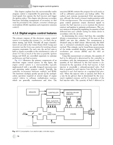
Fig. 4.1-1 illustrates the primary components of an accordance with the instantaneous control mode. The
electronic engine control system. In this figure, the quantity of fuel delivered by the fuel injector is de-
engine control system is a microcontroller, typically termined by the operation of the fuel injector. A fuel
implemented with a specially designed microprocessor injector is essentially a solenoid-operated valve. Fuel
and operating under program control. Typically, the that is supplied to each injector from the fuel pump is
controller incorporates hardware multiply and ROM. supplied to each fuel injector at a regulated fuel pres-
The hardware multiply greatly speeds up the multipli- sure. When the injector valve is opened, fuel flows at
cation operation required at several stages of engine a rate R f (in gal/sec) that is determined by the (con-
control relative to software multiplication routines, stant) regulated pressure and by the geometry of the
which are generally cumbersome and slow. The fuel injector valve. The quantity of fuel F delivered to
SENSORS CONTROLLER IGNITION DRIVER
CIRCUITS
FUEL INJECTOR
DRIVER CIRCUITS
EGR
AIR FUEL VALVE
MAF INJECTORS ENGINE
EGR FUEL
Fig. 4.1-1 Components of an electronically controlled engine.
78