
Page 88 - Automotive Engineering
P. 88
Digital engine control systems CHAPTER 4.1
HEGO (One or two) heated EGO sensor(s) 4.1.4.2 Engine warm-up
POS/RPM Crankshaft angular position and RPM
sensor cycle camshaft position sensor for While the engine is warming up, an enriched air/fuel
determining start of each engine cycle ratio is still needed to keep it running smoothly, but the
required air/fuel ratio changes as the temperature in-
TPS Throttle position sensor
creases. Therefore, the fuel control system stays in the
DPS Differential pressure sensor (exhaust to open-loop mode, but the air/fuel ratio commands con-
intake) for EGR control tinue to be altered due to the temperature changes. The
emphasis in this control mode is on rapid and smooth
The control system selects an operating mode based on engine warm-up. Fuel economy and emission control are
the instantaneous operating condition as determined still a secondary concern.
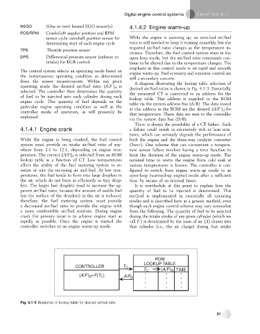
from the sensor measurements. Within any given A diagram illustrating the lookup table selection of
operating mode the desired air/fuel ratio (A/F ) d is desired air/fuel ratios is shown in Fig. 4.1-3. Essentially,
selected. The controller then determines the quantity the measured CT is converted to an address for the
of fuel to be injected into each cylinder during each lookup table. This address is supplied to the ROM
engine cycle. This quantity of fuel depends on the table via the system address bus (A/B). The data stored
particular engine operating condition as well as the at this address in the ROM are the desired (A/F ) d for
controller mode of operation, as will presently be that temperature. These data are sent to the controller
explained.
via the system data bus (D/B).
There is always the possibility of a CT failure. Such
4.1.4.1 Engine crank a failure could result in excessively rich or lean mix-
tures, which can seriously degrade the performance of
While the engine is being cranked, the fuel control both the engine and the three-way catalytic converter
system must provide an intake air/fuel ratio of any- (3wcc). One scheme that can circumvent a tempera-
where from 2:1 to 12:1, depending on engine tem- ture sensor failure involves having a time function to
perature. The correct [A/F] d is selected from an ROM limit the duration of the engine warm-up mode. The
lookup table as a function of CT. Low temperatures nominal time to warm the engine from cold soak at
affect the ability of the fuel metering system to at- various temperatures is known. The controller is con-
omize or mix the incoming air and fuel. At low tem- figured to switch from engine warm-up mode to an
peratures, the fuel tends to form into large droplets in open-loop (warmed-up engine) mode after a sufficient
the air, which do not burn as efficiently as tiny drop- time by means of an internal timer.
lets. The larger fuel droplets tend to increase the ap- It is worthwhile at this point to explain how the
parent air/fuel ratio, because the amount of usable fuel quantity of fuel to be injected is determined. This
(on the surface of the droplets) in the air is reduced; method is implemented in essentially all operating
therefore, the fuel metering system must provide modes and is described here as a generic method, even
a decreased air/fuel ratio to provide the engine with though each engine control scheme may vary somewhat
a more combustible air/fuel mixture. During engine from the following. The quantity of fuel to be injected
crank the primary issue is to achieve engine start as during the intake stroke of any given cylinder (which we
rapidly as possible. Once the engine is started the call F ) is determined by the mass of air (A) drawn into
controller switches to an engine warm-up mode. that cylinder (i.e., the air charge) during that intake
ROM
LOOKUP TABLE
CONTROLLER T C
T C (A/F) D TIME
(A/F) D =F(T ) A/F D
C
Fig. 4.1-3 Illustration of lookup table for desired air/fuel ratio.
81