
Page 87 - Automotive Engineering
P. 87
CH AP TER 4 .1 Digital engine control systems
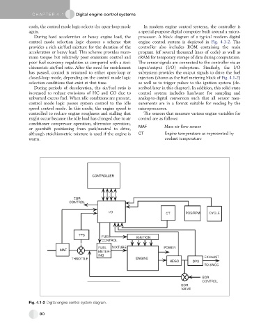
cools, the control mode logic selects the open-loop mode In modern engine control systems, the controller is
again. a special-purpose digital computer built around a micro-
During hard acceleration or heavy engine load, the processor. A block diagram of a typical modern digital
control mode selection logic chooses a scheme that engine control system is depicted in Fig. 4.1-2. The
provides a rich air/fuel mixture for the duration of the controller also includes ROM containing the main
acceleration or heavy load. This scheme provides maxi- program (of several thousand lines of code) as well as
mum torque but relatively poor emissions control and rRAM for temporary storage of data during computation.
poor fuel economy regulation as compared with a stoi- The sensor signals are connected to the controller via an
chiometric air/fuel ratio. After the need for enrichment input/output (I/O) subsystem. Similarly, the I/O
has passed, control is returned to either open-loop or subsystem provides the output signals to drive the fuel
closed-loop mode, depending on the control mode logic injectors (shown as the fuel metering block of Fig. 4.1-2)
selection conditions that exist at that time. as well as to trigger pulses to the ignition system (de-
During periods of deceleration, the air/fuel ratio is scribed later in this chapter). In addition, this solid-state
increased to reduce emissions of HC and CO due to control system includes hardware for sampling and
unburned excess fuel. When idle conditions are present, analog-to-digital conversion such that all sensor mea-
control mode logic passes system control to the idle surements are in a format suitable for reading by the
speed control mode. In this mode, the engine speed is microprocessor.
controlled to reduce engine roughness and stalling that The sensors that measure various engine variables for
might occur because the idle load has changed due to air control are as follows:
conditioner compressor operation, alternator operation,
or gearshift positioning from park/neutral to drive, MAF Mass air flow sensor
although stoichiometric mixture is used if the engine is CT Engine temperature as represented by
warm. coolant temperature
CONTROLLER
EGR
CONTROL
I/O
CT POS/RPM CYCLE
TPS
FUEL IGNITION
CONTROL
FUEL MIXTURE POWER
MAF
METER-
ING
THROTTLE ENGINE EXHAUST
HEGO DPS
TO 3WCC
EGR
CONTROL
EGR
VALVE
Fig. 4.1-2 Digital engine control system diagram.
80