
Page 81 - Autonomous Mobile Robots
P. 81
64 Autonomous Mobile Robots
becomes acceptable for objects that are small and cylindrical in shape, making
their RCS approximately view-point invariant, such as lamp posts, trees, etc.,
which can be used for outdoor navigation.
2.5 CONSTANT FALSE ALARM RATE PROCESSOR FOR TRUE TARGET
RANGE DETECTION
To extract the true range values, previous methods have used a power threshold
on the range bins (the closest power value to exceed some threshold gives the
closest object) [9] or constant false alarm rate (CFAR) techniques [21,24]. The
problem with thresholding is, it requires manual adjustment of the threshold as
the RCS of objects in an outdoor natural environment will vary. The function
of CFAR processors is to maintain a constant and low rate of false alarms in
detecting true range values [25].
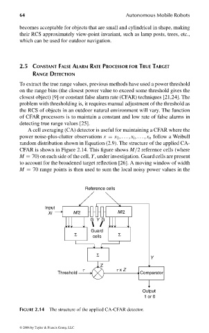
A cell averaging (CA) detector is useful for maintaining a CFAR where the
power noise-plus-clutter observations x = x 1 , ... , x i , ... , x n follow a Weibull
random distribution shown in Equation (2.9). The structure of the applied CA-
CFAR is shown in Figure 2.14. This figure shows M/2 reference cells (where
M = 70) on each side of the cell, Y, under investigation. Guard cells are present
to account for the broadened target reflection [26]. A moving window of width
M = 70 range points is then used to sum the local noisy power values in the
Reference cells
Input
Xi M/2 M/2
G Y G
Guard
Σ cells Σ
Σ
Y
Z
t t x Z
Threshold Comparator
Output
1 or 0
FIGURE 2.14 The structure of the applied CA-CFAR detector.
© 2006 by Taylor & Francis Group, LLC
FRANKL: “dk6033_c002” — 2006/3/31 — 17:29 — page 64 — #24