
Page 146 - Autonomous Mobile Robots
P. 146
Data Fusion via Kalman Filter 129
rotates with the Earth. A local geodetic frame has its origin fixed on the surface
of the earth and axes aligned with the directions of true north, east, and down
(along the parallel to the ellipsoid normal vector to complete the right-handed
coordinate frame).
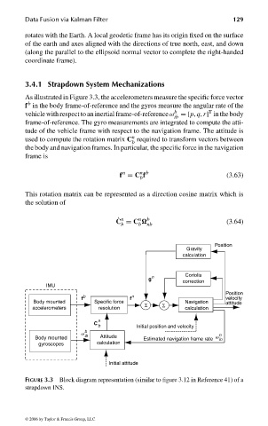
3.4.1 Strapdown System Mechanizations
As illustrated in Figure 3.3, the accelerometers measure the specific force vector
b
f in the body frame-of-reference and the gyros measure the angular rate of the
T
b
vehicle with respectto an inertial frame-of-referenceω =[p, q, r] in thebody
ib
frame-of-reference. The gyro measurements are integrated to compute the atti-
tude of the vehicle frame with respect to the navigation frame. The attitude is
n
used to compute the rotation matrix C required to transform vectors between
b
the body and navigation frames. In particular, the specific force in the navigation
frame is
n b
n
f = C f (3.63)
b
This rotation matrix can be represented as a direction cosine matrix which is
the solution of
n
˙ n
C = C b (3.64)
b b nb
Position
Gravity
calculation
Coriolis
g n
correction
IMU
Position
f b f n velocity
Body mounted Specific force Σ Navigation attitude
accelerometers resolution Σ calculation
n
C
b Initial position and velocity
v b n
Body mounted ib Attitude Estimated navigation frame rate v in
gyroscopes calculation
Initial attitude
FIGURE 3.3 Block diagram representation (similar to figure 3.12 in Reference 41) of a
strapdown INS.
© 2006 by Taylor & Francis Group, LLC
FRANKL: “dk6033_c003” — 2006/3/31 — 16:42 — page 129 — #31