
Page 195 - Autonomous Mobile Robots
P. 195
Landmarks and Triangulation in Navigation 179
C D
A’
A B
B’
u
x
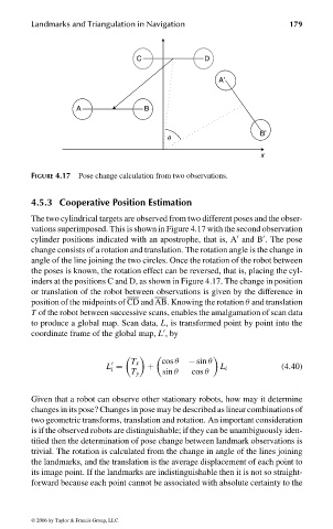
FIGURE 4.17 Pose change calculation from two observations.
4.5.3 Cooperative Position Estimation
The two cylindrical targets are observed from two different poses and the obser-
vations superimposed. This is shown in Figure 4.17 with the second observation
cylinder positions indicated with an apostrophe, that is, A and B . The pose
change consists of a rotation and translation. The rotation angle is the change in
angle of the line joining the two circles. Once the rotation of the robot between
the poses is known, the rotation effect can be reversed, that is, placing the cyl-
inders at the positions C and D, as shown in Figure 4.17. The change in position
or translation of the robot between observations is given by the difference in
position of the midpoints of CD and AB. Knowing the rotation θ and translation
T of the robot between successive scans, enables the amalgamation of scan data
to produce a global map. Scan data, L, is transformed point by point into the
coordinate frame of the global map, L ,by
T x cos θ − sin θ
L = + L i (4.40)
i
T y sin θ cos θ
Given that a robot can observe other stationary robots, how may it determine
changes in its pose? Changes in pose may be described as linear combinations of
two geometric transforms, translation and rotation. An important consideration
is if the observed robots are distinguishable; if they can be unambiguously iden-
tified then the determination of pose change between landmark observations is
trivial. The rotation is calculated from the change in angle of the lines joining
the landmarks, and the translation is the average displacement of each point to
its image point. If the landmarks are indistinguishable then it is not so straight-
forward because each point cannot be associated with absolute certainty to the
© 2006 by Taylor & Francis Group, LLC
FRANKL: “dk6033_c004” — 2006/3/31 — 16:42 — page 179 — #31