
Page 197 - Autonomous Mobile Robots
P. 197
Landmarks and Triangulation in Navigation 181
A’
O’ A
M
O
B’ B
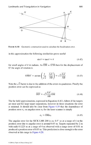
FIGURE 4.18 Geometric construction used to calculate the localization error.
in this approximation the following similarities prove useful
sin θ ≈ tan θ ≈ θ (4.42)
for small angles of θ in radians. As OM = O M then for the displacement of
O the angle of rotation is
2 AA √ AA
ˆ
OMO = arctan √ ≈ 2 (4.43)
2 AB AB
√
Note the 2 factor is due to the addition of the errors in quadrature. Finally the
position error can be expressed as
√ AA
OO ≈ 2 OM (4.44)
AB
The far field approximation, expressed in Equation (4.41), falters if the targets
are near and for large target separations, however in these situations the error
is minimal. It should also be clear from Figure 4.19 that the dependence of
position error σ x on angular error σ θ for the laser scanner is simply
σ x ≈ OMσ θ (4.45)
◦
The angular error for the SICK LMS 200 is ca. 0.5 so at a range of4mthe
position error due to angular error is around 0.03 m. Targets separated by 2 m
with radii 0.1225 m at a range of 4 m observed with a range error of 0.01 m
produced a position error of 0.03 m. This prediction is close enough to the error
observed at this range in Figure 4.20.
© 2006 by Taylor & Francis Group, LLC
FRANKL: “dk6033_c004” — 2006/3/31 — 16:42 — page 181 — #33