
Page 48 - Autonomous Mobile Robots
P. 48
Visual Guidance for Autonomous Vehicles 31
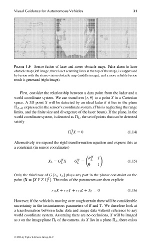
FIGURE 1.9 Sensor fusion of laser and stereo obstacle maps. False alarm in laser
obstacle map (left image, three laser scanning lines at the top of the map), is suppressed
by fusion with the stereo vision obstacle map (middle image), and a more reliable fusion
result is generated (right image).
First, consider the relationship between a data point from the ladar and a
world coordinate system. We can transform {r, θ} to a point X in a Cartesian
space. A 3D point X will be detected by an ideal ladar if it lies in the plane
Z=0 expressed in the sensor’s coordinate system. (This is neglecting the range
limits, and the finite size and divergence of the laser beam). If the plane, in the
world coordinate system, is denoted as L , the set of points that can be detected
satisfy
T
X = 0 (1.14)
L
Alternatively we expand the rigid transformation equation and express this as
a constraint (in sensor coordinates)
W
R L T
W
X L = G X G W = (1.15)
L L
0 1
Only the third row of G [r 3i T Z ] plays any part in the planar constraint on the
T
point {X =[XY Z 1] }. The roles of the parameters are then explicit:
r 31 X + r 32 Y + r 33 Z + T Z = 0 (1.16)
However, if the vehicle is moving over tough terrain there will be considerable
uncertainty in the instantaneous parameters of R and T. We therefore look at
a transformation between ladar data and image data without reference to any
world coordinate system. Assuming there are no occlusions, X will be imaged
as x on the image plane I of the camera. As X lies in a plane L , there exists
© 2006 by Taylor & Francis Group, LLC
FRANKL: “dk6033_c001” — 2006/3/31 — 16:42 — page 31 — #31