
Page 125 - Basic Structured Grid Generation
P. 125
114 Basic Structured Grid Generation
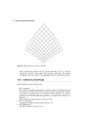
Fig. 4.35 Algebraic grid based on parabolic co-ordinates.
x
where r denotes the position vector and the subscripts bl, tl, br, tr stand for
y
‘bottom left’, ‘top left’, ‘bottom right’, and ‘top right’, respectively. The cartesian
co-ordinates of the four corners of the quadrilateral must be specified by the user.
4.6.4 Subdirectory: Book/tfi.gds
In this subdirectory there are three files.
1. File: Transfinite.f
This code uses transfinite interpolation to generate a planar two-dimensional grid.
The boundaries of the physical domain are prescribed by specifying the cartesian
co-ordinates of boundary points in a subroutine called ‘boundary’. An option is
included to deal with three particular geometries: (a) a square (b) an annulus (c) a
trapezium.
Some examples of grids are shown in figs 4.27–4.30.
2. File: Two-boundary.f
A typical grid around an airfoil is shown in Fig. 4.31.
3. File: Multisurface.f
Examples are shown in figs 4.32–4.34.