
Page 460 - Battery Reference Book
P. 460
Float CP charging of lead-acid batteries 4515
45.2 Shallow cycle CP charging of condition the constant potential and limiting current
lead-acid batteries should be increased. The chargng conditions are:
A battery is classified in this category when 5-50% 1. Constant potential: 2.45-2.50 V/cell.
of its rated capacity has been removed. Under this 2. Limiting current: 20-50% of rated capacity.
condition the constant potential and limiting current 3. Recharge time: limited to 12-20 h; should capacity
should be decreased from the values required for deep appear to be decreasing, charge time should be
service. The charging conditions are: increased periodically to 24-30 h.
1. Constant potential: 2.40-2.56 V/cell.
2. Limiting ciment: 10-15% of rated capacity. 45.4 Float CP charging of lead-acid
3. Charge time: 10-18h; should capacity appear to batteries
be decreasing, charge time should be increased
periodically to 28-30 h. A battery on float service is one subjected to contin-
uous charge and is called on to perform only in case
Taper charging with constant potential, the simplest of emergency. Under these conditions the battery is
method of charging, is satisfactory for charging bat- charged at a constant potential sufficient to maintain it
teries in cyclic service. This method requires control at full charge. Charging conditions are:
of overcharging and of battery heating, both of which
adversely affect battery life. In general, battery life is 1. Constant potential: 2.28-2.30V/cell.
shorter than is obtained in the other charging methods 2. Limiting current: 1-20% of rated capacity.
discussed. 3. Charge time: continuous.
45.3 Deep cycle CP charging of All lead-acid batteries will charge most efficiently
lead-acid batteries in the range of 15-30°C. When float charging is car-
ried out under conditions where the battery tempera-
A battery is cllassified in this category when 50- 100% ture does not fall outside the limit 0-40°C there is
of its rated capacity has been removed to the end- no requirement for temperature compensation to be
voltage specified by the manufacturer. Under this built into the charger to enhance charge efficiency.
t
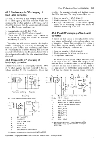
Transformer rectifier Regulator
Smoothing T, Transformer, d.c. 13 V (r.m.s.), 1-3 A (r.m.5.)
(a) Typical constant-voltage charging circuit D,, D, 100 V, 1 A diode
C, 50 V, 470 pF electrolytic condenser
TR, MJ2840 10 A 60 V 150 W (Motorola)
IC LM723C (National Semiconductor)
R, 4.7 n. 112 W 3
R, 5.1 kn, 1/4W
R, 3.9 kn, 114 W
R, 7.5 kn, 114 W
R, 8.2 kn, 1/4W
XF, 6.3 V a.c. XMFR VR 2kn
D, 1 A, 1OOPIV C, 50 V, 1000 pF
C, 1000 pF, 50 W V d.c. (b) Constant-voltage current-limited charger comprising
R, 2.5Q. 5W IC LM723C voltage regulator (for 12 V d.c. output
R, 2.5 kn, 112 W 0.42 A max.)
VR 500Q 112 W
IC LM309 National Semiconductor
(c) Constant-voltage charging circuit comprising IC LM3091C
Figure 45.4 Charging circuits for Yuasa sealed lead-acid batteries (Courtesy of Yuasa)