
Page 464 - Battery Reference Book
P. 464
Voltage-limited taper current charging of alkaline manganese dioxide batteries 46/3
The recommended method for charging alkaline sec- The basic characteristics of sealed alkaline man-
ondary batteries is the use of voltage-limited taper ganese dioxide rechargeable cells when using voltage-
current charging. This method offers the maximum limited taper current charging are given in Table 46.1
cycle life and consequently the lowest battery oper- (based on a 6 h charge period).
ating costs. Cycle life can be as much as twice that A regulator providing voltage regulation of 2-3% at
obtained with other methods of charging. Although low current values is adequate. Poorer regulation when
constant-current charging can be used for this type of the battery is first placed on charge and the voltage is
battery, with c’onsequent loss of cycle life, it is recom- low is often satisfactory. The regulator output volt-
mended that careful enquiries be made before such age is adjusted to the battery end-of-charge voltage.
charging methsods are contemplated. Correct battery voltage is determined by the number
Batteries should not be charged continuously, or of cells and cell voltages given in Table 46.1. The
float charged for extended periods, after the charge cur- current-limiting resistance (the total current-limiting
rent has returned 120% of the ampere hours removed resistance consists of the series resistance plus inher-
on previous discharge. ent resistance of the regulator circuit, which may vary
A rechargeable alkaline manganese dioxide battery with design and component selection) should limit the
must not be discharged completely. For best results, the initial current to the 4-6 h rate at start of charge when
rated capacity of the battery should not be exceeded the battery voltage is low. A typical starting voltage
on discharge. During deep discharge a secondary elec- after withdrawal of rated capacity is 1.30- 1.35 V/cell.
trochemical reaction takes place. This reaction is not The maximum recommended initial charge currents at
reversible and will seriously reduce the battery cycle these voltages are shown in Table 46.1.
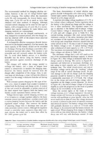
The minimum voltage that a cell will reach at the
life. To avoid1 short battery service, it is therefore end of the recommended discharge capacity is shown
desirable that the device using the battery contain in Figure 46.1. This voltage is measured while the dis-
some provision against excessive discharge of the charge current is flowing. The curves in Figure 46.1
battery. represent cell behaviour at maximum discharge cur-
The charger will replace the energy needed to rent rating to rated capacity and a minimum of 16 h
recharge the battery, and a timer or ampere hour recharge time. The initial closed-circuit and end-of-
control is unnecessary to monitor the charging time. discharge voltage curves give the ‘working’ voltage
However, the battery should be removed from the range of the cell at various discharge levels. To pre-
charger after completion of the charge. Also, to pre- vent damage to the cell on charge cycle the charging
vent deep cell discharge, a timer will provide effective potential should be limited to about 1.8Vkell with
control over the energy withdrawn from the cell during a permissible maximum of 1.75 V/cell. The voltage
any cycle. rise on the charge and end-of-charge voltage value is
With constant-current charging for this type of bat- dependent on the charge current character. As shown
tery, a d.c. timer or ampere hour counter is needed to in Figure 46.1, the end-of-charge voltage will decrease
control both the discharge and charge cycles. A system slightly as cycle life progresses as the result of gradual
of this sort would be adjustable to permit removal of change in the reversibility of the system.
the rated ampere hour capacity from the battery and Since the current tapers as the result of battery
thereby ensure: maximum battery service life. voltage increase, or is ‘voltage responsive’, the end-of-
Voltage-limited taper current charging involves use charge current will increase as cycling progresses. The
of an inexpensive voltage regulator added to the basic current will equilibrate at some specific value but will
constant-current type transformer-rectifier circuit with never reach zero or shut-off since the voltage decreases
a current-limiting resistor between the battery and the as current is reduced as the result of internal resistance
regulated output voltage. This removes the burden and chemical reaction. The battery voltage after charge
of adjusting charge time to discharge time and pro- will gradually decrease to a value of 1.5 Vkell when
vides automatic current control. Although the regulator the charger is disconnected and the battery remains on
circuit is somewhat more expensive than other com- open circuit. When changing from charge to discharge
mon circuits, the initial cost is more than offset by cycle with no time delay between, the battery voltage
50- 100% greater cycle life. decay rate will vary with discharge current. At rates
Table 46.1 Basic: characteristics of sealed alkaline manganese dioxide cells when using voltage-limited taper current charging
Cell size Average operating voltage Maximum initial charging Current-limiting Source voltage
at maximum current (V) current at 1.3 V/cell (A) resistance (Wcell) limit (Vkell)
D 1.0-1.2 0.6 0.8 1.70- 1.75
G 1.0- 1.2 1.12 0.4 I .70- 1.75