
Page 466 - Battery Reference Book
P. 466
Voltage-limited taper current charging of alkaline manganese dioxide batteries 46f5
7.2K --- Recommended (linear) equivalent to 1.3 Vlcell is connected for the battery
to be charged and Rd is selected to limit the charge
1 .o
- Acceptable current to recommended values. The battery should
be disconnected from the charger when the charge
5 0.8 circuit is not energized to prevent discharge through
c
E 0.6 resistance R3.
a The suggested linear taper current for the battery
0
0.4 quoted above (Union Carbide Eveready 561) and the
actual current characteristic obtained with the circuit
0.2
of Figure 46.2 are shown in Figure 46.3. The current
0 characteristic can be tailored by selection of compon-
13 14 15 16 17 18 ents. The curves shown were obtained using the com-
Battery voltage (V) ponent values shown in Figure 46.2. The permissible
deviation of charge current from that indicated sug-
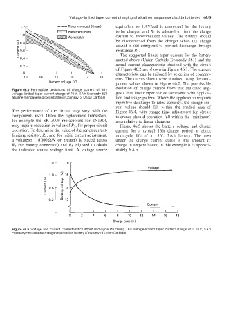
Figure 46.4 Permissible deviations of charge current of 16 h
voltage-limited taper current charge of 15V, 5Ah Eveready 561 gests that linear taper varies somewhat with applica-
alkaline manganese dioxide battery (Courtesy of Union Carbide) tion and usage pattern. Where the application requires
repetitive discharge to rated capacity. the charge cur-
rent values should fall within the shaded area of
The performance of the circuit may vary with the Figure 46.4, with charge time adjustment for circuit
components used. Often the replacement transistors, tolerance should operation fall within the 'minimum'
for example the SK 3009 replacement for 2N1304, area relative to linear character.
may require reduction in value of R3, for proper circuit Figure 46.5 shows the battery voltage and charge
operation. To determine the value of the series current- current for a typical 16h charge period at about
limiting resistor, Rd, and for initial circuit adjustment, mid-cycle life of a 15V, 5Ah battery. The area
a voltmeter (10 000 C22N or greater) is placed across under the charge current curve is the amount of
R3 (no battery connected) and R3 adjusted to obtain charge in ampere hours; in this example it is approxi-
the indicated source voltage limit. A voltage source mately 6 Ah.
0 2 4 6 8 10 12 14 16 18
Charge time (h)
Figure 46.5 Voltage and current characteristics about mid-cycle life during 16 h voltage-limited taper current charge of a 15V, 5Ah
Eveready 561 alltaline manganese dioxide battery (Courtesy of Union Carbide)