
Page 592 - Battery Reference Book
P. 592
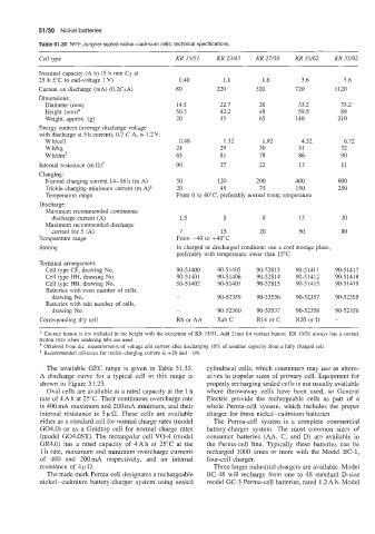
51/30  Nickel batteries

            Table 51.30  NlFE Jungner sealed nickel-cadmium  cells: technical specifications
                                                                                           ~~~
            Cell type                           KR 15/51   KR 23/43   KR 27/50   KR 35/62   KR 35/92
            Nominal capacity (A h) (5 h rate C5  at
            25 f 5°C to end-voltage 1 V)         0.40        1.1       1.6       3.6         5.6
            Current on discharge (mA) (0.2C5A)   80        220       320        720       1120
            Dimensions:
             Diameter (mm)                      14.5        22.7      26         33.2       33.2
             Height (mm)*                       50.3        42.2      48         59.5       89
             Weight, approx. (g)                20          45        65        140        210
            Energy content (average discharge voltage
            with discharge at 5 h current), 0.2 C A, is 1.2V:
             W Wcell                             0.48        1.32      1.92      4.32        6.72
             wmg                                24          29        30         31         32
             W Wdm3                             65          81        78         86         90
            Internal resistance (ma)+           90          27        22         13         11
            Charging:
             Normal charging current  14-16h  (m A)   50   120       200        400        600
             Trickle charging minimum current (m A)*   20   45        75        150        250
             Temperature range                  From 0 to 40"C, preferably normal room temperature
            Discharge:
             Maximum recommended continuous
               discharge current (A)             1.5         5         8         15         20
             Maximum recommended discharge
               current for 5 (A)                 7          15        20         50         80
            Temperature range                   From -40  to +40"C
            Storing                             In charged or discharged condition: use  a cool storage place,
                                                preferably with temperature lower than  15°C
            Terminal arrangement:
             Cell type CF, drawing No.          90-51400   90-51405   90-52813   90-5141 1   90-51417
             Cell type HH, drawing No.          90-51401   90-51406   90-52814   90-51412   90-51418
             Cell type HB, drawing No.          90-51402   90-51407   90-52815   90-51413   90-51419
             Batteries with even number of  cells,
               drawing No.                      -          90-52359   90-53536   90-52357   90-52355
             Batteries with odd number of cells,
               drawing No.                      -          90-52360   90-53537   90-52358   90-52356
            Corresponding dry cell              R6orAA     Sub C     R14 orC    R20 orD   -

            *  Contact button is not  included in the height with the exception of  KR  15/51. Add 2mm for contact button. KR  15/51 always has a contact
            button even when soldering tabs are used
             Obtained from d.c. measurements of voltage and current after discharging 10% of  nominal capacity from a fully charged cell
            *  Recommended tolerance for trickle charging current is +20  and -0%
              The available  GEC range  is given  in  Table 51.33.   cylindrical cells, which consumers  may use as altern-
            A  discharge  curve for  a  typical  cell in this  range  is   atives to popular  sizes of primary  cell. Equipment  for
            shown in Figure 51.23.                      properly recharging sealed cells is not usually available
              Oval cells are available at a rated capacity at the 1 h   where  throwaway  cells  have  been  used,  so  General
            rate of 4A h at 25°C. Their continuous overcharge rate   Electric  provide  the  rechargeable  cells  as  part  of  a
            is 400 mA maximum and 200 mA minimum, and their   whole  Perma-cell  system,  which  includes  the  proper
            internal  resistance  is 5 p C2.  These cells  are  available   charger for these nickel-cadmium  batteries.
            either as a standard cell for normal charge rates (model   The  Perma-cell  system  is  a  complete commercial
            G04.0) or as a  Goldtop cell for normal  charge  rates   battery-charger  system.  The  most  common  sizes  of
            (model G04.0ST). The rectangular  cell VO-4 (model   consumer batteries  (AA,  C,  and  D)  are  available  in
            GR4.0) has  a rated  capacity  of  4Ah at  25°C at  the   the  Perma-cell  line.  Typically  these  batteries  can  be
            1 h rate,  maximum and minimum overcharge currents   recharged  1000 times  or more  with  the Model BC-1,
            of  400  and  200mA  respectively,  and  an  internal   four-cell  charger.
            resistance  of 4 p 0.                         Three larger industrial chargers are available. Model
              The trade mark Perma-cell designates a rechargeable   BC-48 will  recharge  from one to 48 standard  D-size
            nickel-cadmium  battery-charger  system using  sealed   model GC-3 Perma-cell batteries, rated  1.2 Ah. Model