
Page 197 - 02. Subyek Computer Aided Design - Beginner’s Guide to SOLIDWORKS 2019- Level 1 by Alejandro Reyes
P. 197
Part Modeling
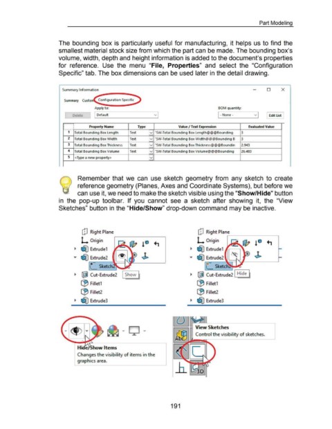
The bounding box is particularly useful for manufacturing, it helps us to find the
smallest material stock size from which the part can be made. The bounding box's
volume, width, depth and height information is added to the document's properties
for reference. Use the menu "File, Properties" and select the "Configuration
Specific" tab. The box dimensions can be used later in the detail drawing.
Summary Information 0 X
~--..............
Apply to: BOM quantity:
I Default 1-None - Edit list
Property Name Type Val. ue I Text Expression Evaluated Value
...............
1 Total Bounding Box Length Text v "SW-Total Bounding Box Length@@@Bounding 3
2 Total Bounding Box Width Text v "SW-Total Bounding Box Width@@@Bounding B 3
3 Total Bounding Box Thickness Text v ·sw-Total Bounding Box Thickness@@@Boundin .2.943
4 Total Bounding Box Volume Text v "SW-Total Bounding Box Volume@@@Bounding 26.483
5 <Type a new property> v
-
. Remember that we can use sketch geometry from any sketch to create
) reference geometry (Planes, Axes and Coordinate Systems), but before we
can use it, we need to make the sketch visible using the "Show/Hide" button
in the pop-up toolbar. If you cannot see a sketch after showing it, the "View
Sketches" button in the "Hide/Show" drop-down command may be inactive.
[!J Right Plane [!J Right Plane
L Origin ..--------.. ~------~
!Q L Origin
~ ~ Extrudel ~ ~ Extrudel
,.. ~ Extrude2 J> ,.. ~ Extrude2
L_ Sketch [_ Sketch~~
,------,
~ ~ Cut-Extrude2 ~ ~ Cut-Extrude2 Hide
lj3 Filletl lj3 Filletl
(9 Fillet2 (9 Fillet2
~ ~ Extrude3 ~ ~ Extrude3
Changes the visibility of items in the
graphic:s area.
191