
Page 192 - 02. Subyek Computer Aided Design - Beginner’s Guide to SOLIDWORKS 2019- Level 1 by Alejandro Reyes
P. 192
Beginner's Guide to SOLIDWORKS 2019- Level I
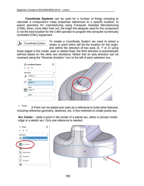
Coordinate Systems can be used for a number of things including to
calculate a component's mass properties referenced to a specific location, to
export geometry for manufacturing using Computer Assisted Manufacturing
(CAM), when, more often than not, the origin the designer used for the component
is not the best location for the CAM operator to program the computer numerically
controlled (CNC) equipment.
t _ - To create a Coordinate System we need to select a
.._~ __ Coordinate System_ vertex or point which will be the location for the origin,
and define the direction of two axes (X, Y or Z) using
linear edges in the model, axes or sketch lines; the third direction is automatically
defined based on the other two directions. Notice that an axis direction can be
reversed using the "Reverse direction" icon to the left of each selection box.
).. Coordinate System (1)
Selections
).. I Vertex< 1 >
X axis:
~ Edge<2>
Y axis:
~ I Edge <3> •
I
•
\
•
Z axis: •
~ L---1 -------1 , •• , .
o Point
A Point can be added and used as a reference to build other features,
including reference geometry, sketches, etc. A few methods to create points are:
Arc Center - Adds a point in the center of a planar arc, either a circular model
edge or a sketch arc. Only one reference is needed.
! ! -, ·'
c Point .lrl·'·' .· -·· ...... , .·
' ,
I
•
' • -- .... _ __ -··--·""' .... .;· •
•.
I •
Selections ••
• '
•• ....... ••• ..... ~.\._ ........... \ ···",.l
- -····
,.
,
, ~ . \ '·-- .............. - • •••
.
' ··· . ,,,.··' I \ \ \. ' \ ~/
o
/
[ (o") Arc Center ' • '
.....
- ... ···--L ,., ··' • ... -. ' ..., ' ....... ... - -···'
---···
0
---
.
-..... ... __ .J,.. .. - -··· · · -· ......... . - •
•••
•• .....
~~~ Intersection • '
l..b I Projection
l/ 1 On point
186