
Page 189 - 02. Subyek Computer Aided Design - Beginner’s Guide to SOLIDWORKS 2019- Level 1 by Alejandro Reyes
P. 189
Part Modeling
Auxiliary Geometry:
r:::0. Auxiliary geometry includes
\'--/) Planes, Axes, Coordinate [ij wrap
Systems, Points, Mate
Reference C rves
References and Center of Mass. All of ~ Intersect Geometry lnstant3D
these can be created from the
"Reference Geometry" icon in the ~ c:J Mirror
Features tab in the CommandManager.
Reference geometry can be used for Plane
many reasons, including locating
features and components, as reference, ).. Coordinate System
or to use as part of a feature. An axis
o Point
can be used to define the direction for a
circular pattern and planes to add -$- Center of Mass
sketch geometry. ' Bounding Box
L e@ Mate Reference
The main options to create Planes were covered previously; here are other types
of Reference Geometry. Open the 'Knob' part from the included files to practice.
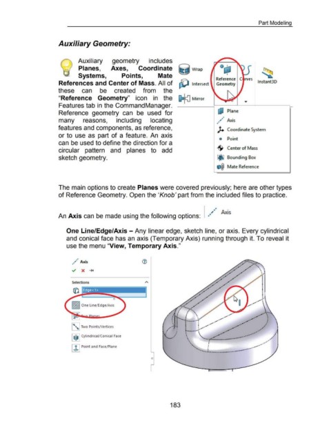
An Axis can be made using the following options:
One Line/Edge/Axis -Any linear edge, sketch line, or axis. Every cylindrical
and conical face has an axis (Temporary Axis) running through it. To reveal it
use the menu "View, Temporary Axis."
•
,. Ax"
• lS ~-~-
••
/ .. ,
•
• . ·' ~"' ·,
.,·
.
"' . . . ,.,' "' " ' ' . I
,
"' .· •• "' "' r • '
/•'
Selections .,. .,.·"' / .
•
•
/
#I'.. ""'. ~ ......
•
.,· "" • •
••
• ·"
~·
""
.,.
__ .,.. ,..,.· •
•
."' /
,~'-.. /
~ ?-.....
•
I
. . ' ·,, ,-· ....... · ,.. ··' . . ....
.
. It
/
:
•
•
/
_,
I
•
\
: ........ , .... ____ .,,_ _.,. .,·· :
{ It . I • i / •• _,• I •
I
I
~~~'bl Two PointsNertices _,t~ . - . • I : / i/ ,,• ·' •' ~~
,· : '--· -_....<;~· _,. ..•·
r I • _,• • ' I
---·.
,.,. •
I f:j I Cylindrical/Conical Face •'--· / ·' \ . , . ·-·· ~······· ./ ,I
r
\ . --.. __.. . ,.
.
'"· ' •" ~.
"
i
~ Point and Face/ Plane '· ' . . .. - • • ..- _,..·'
I
• ,
-~~ J ---~
--··-·· ········-····· ..
0
183