Page 20 - 02. Subyek Computer Aided Design - Beginner’s Guide to SOLIDWORKS 2019- Level 1 by Alejandro Reyes
P. 20

Beginner's Guide to SOLIDWORKS 2019- Level I


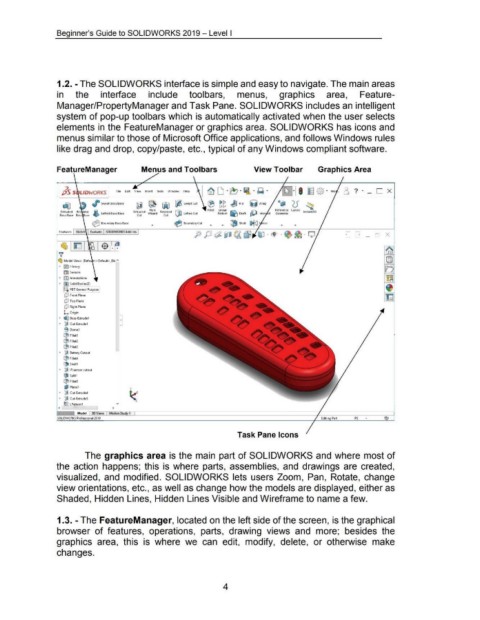
                                    1.2. -The SOLIDWORKS interface is simple and easy to navigate. The main areas


                                    in          the             interface                     include                  toolbars,                     menus,                     graphics                     area,                Feature-


                                    Manager/PropertyManager and Task Pane. SOLIDWORKS includes an intelligent


                                    system of pop-up toolbars which is automatically activated when the user selects


                                    elements in the FeatureManager or graphics area. SOLIDWORKS has icons and


                                    menus similar to those of Microsoft Office applications, and follows Windows rules


                                    like drag and drop, copy/paste, etc., typical of any Windows compliant software.


                                    FeatureManager                                       Menus and Toolbars                                                     View Toolbar                            Graphics Area


                                       }5 S  L/DWORKS                    file  Ed~  View  Insert   Tools  Window  Help


                                        ~                 ,     Swept Boss/Base                                                                                                • "'  (5  ~
                                                                                      ~ ~ ~ ~ SweptCut  ® g g ~ Rib  ijJ Wrap
                                                                                                                                                                                               1  30
                                                                                              Hole            QJD                  Fillet   linear  ~        ..c?ll          Rtference  Curves  ~
                                       Extruded  Rev  lved  i'l  lofted Boss/Base   Extruded  Wizard  Revolved      lofted Cut           Pattern  ~ Draft  p.-"  Inter  ct   Geometry          ns an
                                      Boss/Base  Boss Base  ~                         Cut              Cut

                                                          ~ Boundary Boss/Base                                ~ Boundary Cut        •       •    ~ Shell  i:>l(i  1rror

                                      Features   Sketch   Evaluate   SOliDWORKS Add-Ins
                                                        ,

                                       ~ trn                  I $ ~


                                     ')!
                                     ~ ModeiViews  (Oefa  <<Default>_Dis"

                                      ~  !§) History
                                         II) Sensors
                                      • fAl Annotations
                                      ~  fi) Solid Bodies(2)
                                        ~:::0  PBT General Purpose I

                                         [!1  Front Plane
                                         [!1  Top Plane
                                         [!1  Right Plane

                                         L  Origin
                                      ~  ~ Boss-Extrude1
                                      ~  ~ Cut-Extrude1
                                         8 Dome1

                                         (B Filletl
                                         ij:l Fillet2
                                         (B Fillet3
                                      ~  ~ Battery Cutout

                                         ij:l Fillet4
                                         ~1J Shelll
                                      ~  crlJliR sensor cutout
                                         ()til  Splitl
                                         ij:l FilletS

                                         l)l Planel
                                      ~  iJ Cut-Extrude4
                                      ~  ~ Cut-ExtrudeS

                                         ~I<;  LPattern 1                 v
                                     <                                 >


                                     SOliDWORKS Professiona1201g                                                                                                                                          Editing Part        IPS     •


                                                                                                                                                     Task Pane Icons


                                                      The graphics area is the main  part of SOLIDWORKS and where most of


                                    the  action  happens;  this  is where  parts,  assemblies,  and  drawings are  created,


                                    visualized,  and  modified.  SOLIDWORKS  lets  users Zoom,  Pan,  Rotate,  change


                                    view orientations, etc., as well as change how the models are displayed, either as


                                    Shaded, Hidden Lines, Hidden Lines Visible and Wireframe to name a few.


                                     1.3. -The FeatureManager, located on the left side of the screen, is the graphical


                                    browser  of features,  operations,  parts,  drawing  views  and  more;  besides  the


                                    graphics  area,  this  is  where  we  can  edit,  modify,  delete,  or  otherwise  make


                                    changes.


                                                                                                                                            4
   15   16   17   18   19   20   21   22   23   24   25