Page 301 - 02. Subyek Computer Aided Design - Beginner’s Guide to SOLIDWORKS 2019- Level 1 by Alejandro Reyes
P. 301

Beginner's Guide to SOLIDWORKS 2019- Level I


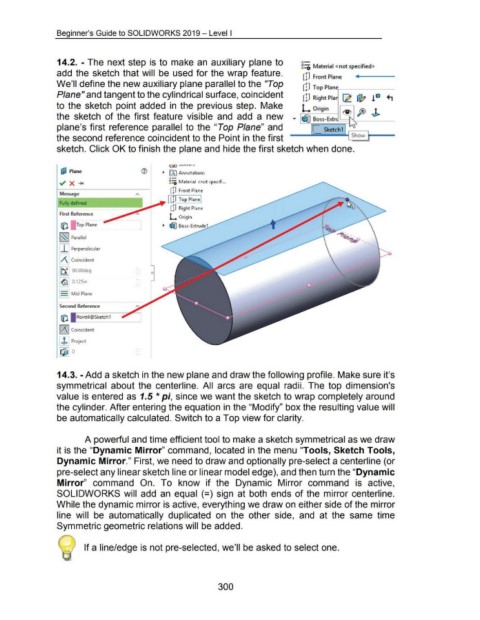
                                     14.2. - The next step  is  to  make an  auxiliary plane to                                                                                              8=i Material <not specified>


                                    add  the  sketch that will  be  used for the wrap feature.                                                                                                 dJ  Front Plane


                                    We'll define the new auxiliary plane parallel to the "Top                                                                                                 [!I  Top PlanG-----


                                    P/ane" and tangent to the cylindrical surface, coincident                                                                                                  cD  Right Pia  ~ ~ ! 10  +,


                                    to  the  sketch  point added  in  the  previous step.  Make                                                                                               L origin                            B


                                    the  sketch  of the first  feature  visible  and  add  a  new  ....  ~ Boss-Extr                                                                                                            F  J>

                                    plane's first reference  parallel  to  the  "Top  Plane"  and                                                                                                   [_ sketch1  .------,


                                    the second reference coincident to the Point in the first                                                                                                                                Show  ~-


                                    sketch. Click OK to finish the plane and hide the first sketch when done.


                                       [j;l  Plane                                                     ._  fAI Annotations

                                                                                                           o-
                                                                                                           &::0 Material  <not specifi ...


                                                                                                            cP Front Plane
                                      Message
                                                                                                          I [!J  Top Plane I
                                      Fully defined
                                                                                                            [p  Right Plane

                                      First Reference
                                                                                                           L  Origin
                                       til       Top Plane                                             ._  ~ Boss-Extrud


                                      ~~~  Parallel


                                      I I I Perpendicular


                                      l/\1 Coincident


                                      1~ 1 9o.oodeg


                                      ~~~  0.125n


                                      I  I Mid Plane


                                      Second Reference

                                       til       Point4@Sketch 1


                                      I/\ I Coincident


                                      I J.l Project

                                      IQ1!] o


                                     14.3. -Add a sketch in the new plane and draw the following profile. Make sure it's


                                    symmetrical  about the  centerline.  All  arcs  are  equal  radii.  The  top  dimension's


                                    value is entered as  1.5 *pi, since we want the sketch to wrap completely around


                                    the cylinder. After entering the equation in the "Modify" box the resulting value will


                                    be automatically calculated. Switch to a Top view for clarity.


                                                      A powerful and time efficient tool to make a sketch symmetrical as we draw


                                    it is the "Dynamic Mirror" command, located in the menu "Tools, Sketch Tools,


                                    Dynamic Mirror." First, we need to draw and optionally pre-select a centerline (or


                                    pre-select any linear sketch line or linear model edge), and then turn the "Dynamic


                                    Mirror"  command  On.  To  know  if  the  Dynamic  Mirror  command  is  active,


                                    SOLIDWORKS will  add  an  equal  (=)  sign  at both  ends of the  mirror centerline.


                                    While the dynamic mirror is active, everything we draw on either side of the mirror


                                    line  will  be  automatically  duplicated  on  the  other  side,  and  at  the  same  time


                                    Symmetric geometric relations will be added.


                                                     If a line/edge is not pre-selected, we'll  be asked to select one.


                                                                                                                                         300
   296   297   298   299   300   301   302   303   304   305   306