
Page 57 - 02. Subyek Computer Aided Design - Beginner’s Guide to SOLIDWORKS 2019- Level 1 by Alejandro Reyes
P. 57
Part Modeling
"'-.. ~ 0 , /
~ /
' ,
......... .. , /
......... /
' ,
' .. ......... l,t' /
/""'
/, ...........
, '
, / ' ...
, / ...
/
/, ...........
Modify
01 @Sketch2
~ ~
IIJ'l I I I I 'I I I I 'I II I 11 II I I 'I I I I H I I 'I I I I 'I II I I 11 II I ••4rt'1'1fJ • • I
-
n
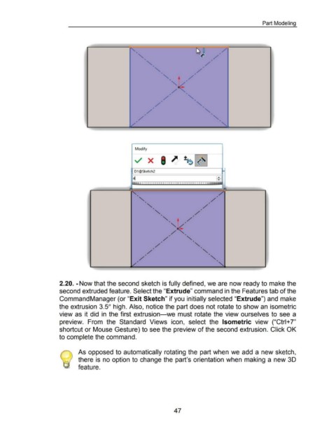
2.20. -Now that the second sketch is fully defined, we are now ready to make the
second extruded feature. Select the "Extrude" command in the Features tab of the
Command Manager (or "Exit Sketch" if you initially selected "Extrude") and make
the extrusion 3.5" high. Also, notice the part does not rotate to show an isometric
view as it did in the first extrusion-we must rotate the view ourselves to see a
preview. From the Standard Views icon, select the Isometric view ("Ctrl+ 7"
shortcut or Mouse Gesture) to see the preview of the second extrusion. Click OK
to complete the command.
As opposed to automatically rotating the part when we add a new sketch,
there is no option to change the part's orientation when making a new 30
feature.
47