
Page 222 - Biaxial Multiaxial Fatigue and Fracture
P. 222
206 A. YARYA NI-FARAHANI
In load histories B3 and B4, two axes of loading start with a phase delay of $=90°: the former
history contains no mean stress, while the latter history contains a transverse mean stress value.
Histories B3 and B4 have non-linear C-shaped load paths (see Fig. l(b)).
(c) Frequency ratio -3: two axes are loaded with a frequency ratio of 3: 1. Histories C1 and
C3 correspond to biaxial tests including no mean value, however, histories C2 and C4 contain
a non-zero transverse mean stress value. Histories C1 and C2 have non-linear Z-shaped load
paths, while histories C3 and C4 have non-linear S-shaped load paths (see Fig. l(c)).
FATIGUE DAMAGE MODEL AND ANALYSIS
Cyclic stress and strain analyses
The stress and strain tensors for a thin-walled tubular specimen are given by Eq (1) and Eq (2),
respectively:
=
g..
I" O 0 E,, :I
Eij = 0 E,,
0
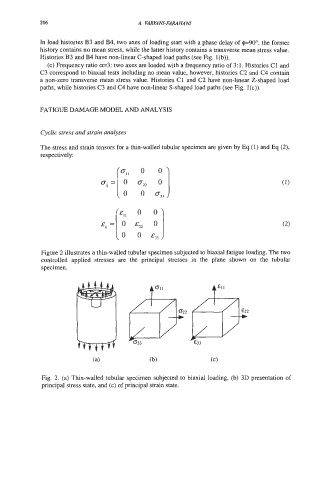
Figure 2 illustrates a thin-walled tubular specimen subjected to biaxial fatigue loading. The two
controlled applied stresses are the principal stresses in the plane shown on the tubular
specimen.
t
Fig. 2. (a) Thin-walled tubular specimen subjected to biaxial loading, (b) 3D presentation of
principal stress state, and (c) of principal strain state.