
Page 227 - Biaxial Multiaxial Fatigue and Fracture
P. 227
Critical Plane-Energy Based Approach for Assessment of Biavial Fatigue Damage where ... 21 1
analysis. Equation (12) has been developed to take into account the damage accumulation due
to stress cycles within a block fatigue loading:
where N corresponds to the number of (TI cycles, i represents the i-th 01 cycle in a block
loading history, subscript b represents the block loading, and subscript f represents the failure.
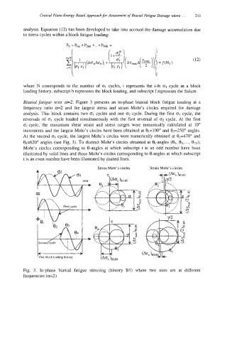
Biaxial fatigue tests -2: Figure 3 presents an in-phase biaxial block fatigue loading at a
frequency ratio a=2 and the largest stress and strain Mohr's circles required for damage
analysis. This block contains two GI cycles and one 02 cycle. During the first crI cycle, the
reversals of (TI cycle loaded simultaneously with the first reversal of 02 cycle. At the first
01 cycle, the maximum shear strain and stress ranges were numerically calculated at 10"
increments and the largest Mohr's circles have been obtained at 01=100" and 02=250" angles.
At the second (TI cycle, the largest Mohr's circles were numerically obtained at 03470" and
04=620" angles (see Fig. 3). To distinct MOWS circles obtained at Bt-angles (01, 02, .... 02~),
Mohr's circles corresponding to 0-angles at which subscript t is an odd number have been
illustrated by solid lines and those Mohr's circles corresponding to %angles at which subscript
t is an even number have been illustrated by dashed lines.
Stress Mohr's circles Strain Mohr's circles
Bl
One block loading history
Fig. 3. In-phase biaxial fatigue stressing (history B1) where two axes are at different
frequencies (ad)