
Page 305 - Biaxial Multiaxial Fatigue and Fracture
P. 305
The Background of Fatigue Limit Ratio of Torsional Fatigue to Rotating Bending Fatigue in ... 289
(-1~m) like a point, and gradually grows as the number of cycles N increases. Then the
crack does not stop propagating due to the work softening effect [16], which finally causes the
specimen to break. This phenomenon is quite different from the case of an annealed carbon
steel, where fatigue process can clearly be divided into crack initiation and crack propagation
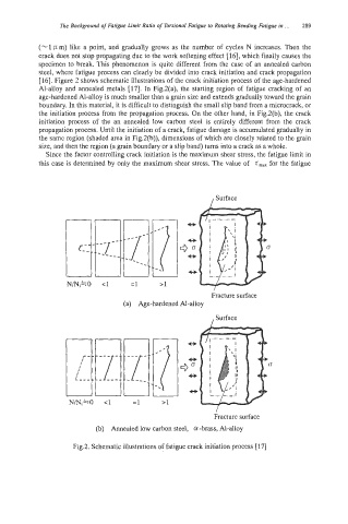
[16]. Figure 2 shows schematic illustrations of the crack initiation process of the age-hardened
Al-alloy and annealed metals [17]. In Fig.2(a), the starting region of fatigue cracking of an
age-hardened Al-alloy is much smaller than a grain size and extends gradually toward the grain
boundary. In this material, it is difficult to distinguish the small slip band from a microcrack, or
the initiation process from the propagation process. On the other hand, in Fig.2(b), the crack
initiation process of the an annealed low carbon steel is entirely different from the crack
propagation process. Until the initiation of a crack, fatigue damage is accumulated gradually in
the same region (shaded area in Fig2(b)), dimensions of which are closely related to the grain
size, and then the region (a grain boundary or a slip band) turns into a crack as a whole.
Since the factor controlling crack initiation is the maximum shear stress, the fatigue limit in
this case is determined by only the maximum shear stress. The value of z,,, for the fatigue
/ Surface
N/Ni=O c1 =I
(a) Age-hardened Al-alloy
, Surface
Fracture surface
(b) Annealed low carbon steel, cx -brass, Al-alloy
Fig.2. Schematic illustrations of fatigue crack initiation process [17]