
Page 371 - Biaxial Multiaxial Fatigue and Fracture
P. 371
Three-Dimensional Crack Growth: Numerical Evaluations and Experimental Tests 355
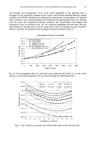
Part-through crack propagation. Even if the notch introduced on the specimen hole is
triangular, for the simulation a quarter circular comer crack has been modelled (because already
available in the BEASY database) but checking that, after the pre-cracking phase, two identical
initial conditions were obtained between the numerical and experimental crack front. Starting
from this point the comparisons between numerical and experimental crack shapes and
propagation times are presented (Fig. 14): the simulated propagation proceed faster than the
experimental one and this turns out to be conservative even if not strongly accurate. The SIF’s
effective along the crack front for each propagation step are presented in Fig. 15.
Total Number of Cycles vs Crack Size
5.00
4.50
4.00 .......
7 3.50
E 3.00
2 2.50 ................. ........
5 2.00 ........ ...............
e!
1.50 ..................
1 .oo .......................
OSO 0.00 2
0 5000 loo00 15000 2oooO 25000 30000 35000 40000
Number of Cycles
Fig. 14. Crack propagation data (C is the break point inside the hole, whilst A is on the visible
surface): an exponential regression line was drawn through the experimental data.
3,6E+02
3,4E+02 +STEPS +STEP6 +STEP7 *STEP8
,. 3.ZEi02
-2 3.0E+02
Y
a
2 2,6E+02
;; . _L .’ ’- - -b
2,4E+02
_ _ _ _ _ ~
2,2E+02
2.OEi02
0.0 0,I 0,2 0,3 0,4 0.5 0,6 0,7 0,8 0,9 1.0
Local Position on Crack Front
Fig. 15. SIF’s effective along the crack front for the elliptical part-through crack.