
Page 309 - Biofuels Refining and Performance
P. 309
288 Chapter Nine
9.4.5 Power-conditioning system [33]
The power-conditioning system is an integral part of a fuel cell system.
It converts the dc electric power generated by the fuel cell into regulated
dc or ac for consumer use. The electrical characteristics of a fuel cell are
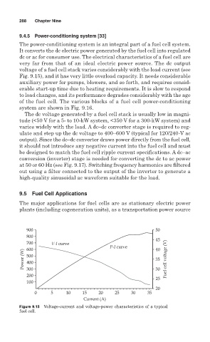
very far from that of an ideal electric power source. The dc output
voltage of a fuel cell stack varies considerably with the load current (see
Fig. 9.15), and it has very little overload capacity. It needs considerable
auxiliary power for pumps, blowers, and so forth, and requires consid-
erable start-up time due to heating requirements. It is slow to respond
to load changes, and its performance degrades considerably with the age
of the fuel cell. The various blocks of a fuel cell power-conditioning
system are shown in Fig. 9.16.
The dc voltage generated by a fuel cell stack is usually low in magni-
tude (<50 V for a 5- to 10-kW system, <350 V for a 300-kW system) and
varies widely with the load. A dc–dc converter stage is required to reg-
ulate and step up the dc voltage to 400–600 V (typical for 120/240-V ac
output). Since the dc–dc converter draws power directly from the fuel cell,
it should not introduce any negative current into the fuel cell and must
be designed to match the fuel cell ripple current specifications. A dc–ac
conversion (inverter) stage is needed for converting the dc to ac power
at 50 or 60 Hz (see Fig. 9.17). Switching frequency harmonics are filtered
out using a filter connected to the output of the inverter to generate a
high-quality sinusoidal ac waveform suitable for the load.
9.5 Fuel Cell Applications
The major applications for fuel cells are as stationary electric power
plants (including cogeneration units), as a transportation power source
900 50
800
45
700 V-I curve
P-I curve 40
600
Power (W) 500 35 Fuel cell voltage (V)
400
300
200 30
25
100
20
0 5 10 15 20 25 30 35
Current (A)
Figure 9.15 Voltage-current and voltage-power characteristics of a typical
fuel cell.