
Page 310 - Biofuels Refining and Performance
P. 310
Fuel Cells 289
120/240-V,
DC link &
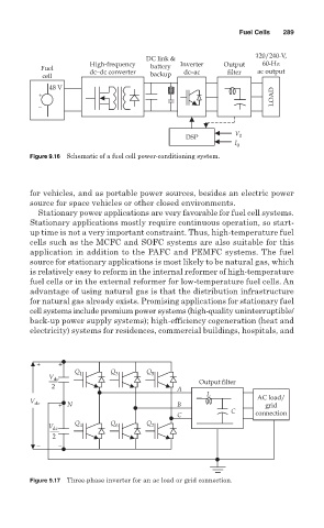
High-frequency Inverter Output 60-Hz
Fuel dc–dc converter battery dc–ac filter ac output
cell backup
48 V
+ LOAD
_
V
DSP 0
I 0
Figure 9.16 Schematic of a fuel cell power-conditioning system.
for vehicles, and as portable power sources, besides an electric power
source for space vehicles or other closed environments.
Stationary power applications are very favorable for fuel cell systems.
Stationary applications mostly require continuous operation, so start-
up time is not a very important constraint. Thus, high-temperature fuel
cells such as the MCFC and SOFC systems are also suitable for this
application in addition to the PAFC and PEMFC systems. The fuel
source for stationary applications is most likely to be natural gas, which
is relatively easy to reform in the internal reformer of high-temperature
fuel cells or in the external reformer for low-temperature fuel cells. An
advantage of using natural gas is that the distribution infrastructure
for natural gas already exists. Promising applications for stationary fuel
cell systems include premium power systems (high-quality uninterruptible/
back-up power supply systems); high-efficiency cogeneration (heat and
electricity) systems for residences, commercial buildings, hospitals, and
+ +
Q 1 Q 3 Q 5
V dc
Output filter
2 A
L
V dc + N B AC load/
grid
C C connection
Q Q Q
V dc 4 6 2
2
− −
Figure 9.17 Three-phase inverter for an ac load or grid connection.