
Page 305 - Biofuels Refining and Performance
P. 305
284 Chapter Nine
source for implantable devices. There is still a lot of work to be done as
there are many unanswered questions; however, the feasibility of con-
structing commercially viable biofuel cell power supplies for a number
of applications is very promising.
9.4 Fuel Cell System
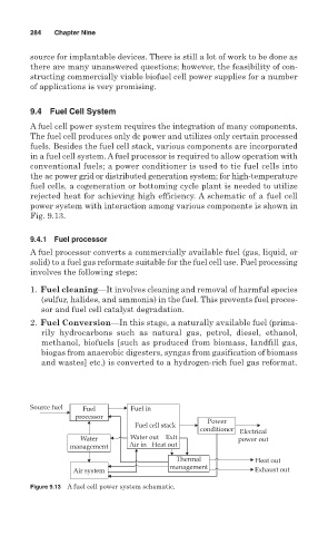
A fuel cell power system requires the integration of many components.
The fuel cell produces only dc power and utilizes only certain processed
fuels. Besides the fuel cell stack, various components are incorporated
in a fuel cell system. A fuel processor is required to allow operation with
conventional fuels; a power conditioner is used to tie fuel cells into
the ac power grid or distributed generation system; for high-temperature
fuel cells, a cogeneration or bottoming cycle plant is needed to utilize
rejected heat for achieving high efficiency. A schematic of a fuel cell
power system with interaction among various components is shown in
Fig. 9.13.
9.4.1 Fuel processor
A fuel processor converts a commercially available fuel (gas, liquid, or
solid) to a fuel gas reformate suitable for the fuel cell use. Fuel processing
involves the following steps:
1. Fuel cleaning—It involves cleaning and removal of harmful species
(sulfur, halides, and ammonia) in the fuel. This prevents fuel proces-
sor and fuel cell catalyst degradation.
2. Fuel Conversion—In this stage, a naturally available fuel (prima-
rily hydrocarbons such as natural gas, petrol, diesel, ethanol,
methanol, biofuels [such as produced from biomass, landfill gas,
biogas from anaerobic digesters, syngas from gasification of biomass
and wastes] etc.) is converted to a hydrogen-rich fuel gas reformat.
Source fuel Fuel Fuel in
processor Power
Fuel cell stack
conditioner Electrical
Water Water out Exit power out
management Air in Heat out
Thermal Heat out
management
Air system Exhaust out
Figure 9.13 A fuel cell power system schematic.