
Page 139 - Biomedical Engineering and Design Handbook Volume 1, Fundamentals
P. 139
116 BIOMECHANICS OF THE HUMAN BODY
Frc
Pbs
Vrc
Rib cage
Pao
Qao
Ppl
Vdi
Diaphragm
Fdi
Vj
j Fj
Pab
Fab
Vab
Abdomen
Pbs
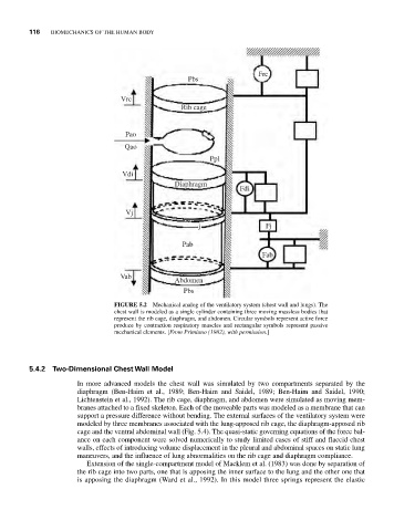
FIGURE 5.2 Mechanical analog of the ventilatory system (chest wall and lungs). The
chest wall is modeled as a single cylinder containing three moving massless bodies that
represent the rib cage, diaphragm, and abdomen. Circular symbols represent active force
produce by contraction respiratory muscles and rectangular symbols represent passive
mechanical elements. [From Primiano (1982), with permission.]
5.4.2 Two-Dimensional Chest Wall Model
In more advanced models the chest wall was simulated by two compartments separated by the
diaphragm (Ben-Haim et al., 1989; Ben-Haim and Saidel, 1989; Ben-Haim and Saidel, 1990;
Lichtenstein et al., 1992). The rib cage, diaphragm, and abdomen were simulated as moving mem-
branes attached to a fixed skeleton. Each of the moveable parts was modeled as a membrane that can
support a pressure difference without bending. The external surfaces of the ventilatory system were
modeled by three membranes associated with the lung-apposed rib cage, the diaphragm-apposed rib
cage and the ventral abdominal wall (Fig. 5.4). The quasi-static governing equations of the force bal-
ance on each component were solved numerically to study limited cases of stiff and flaccid chest
walls, effects of introducing volume displacement in the pleural and abdominal spaces on static lung
maneuvers, and the influence of lung abnormalities on the rib cage and diaphragm compliance.
Extension of the single-compartment model of Macklem et al. (1983) was done by separation of
the rib cage into two parts, one that is apposing the inner surface to the lung and the other one that
is apposing the diaphragm (Ward et al., 1992). In this model three springs represent the elastic