
Page 274 - Biomedical Engineering and Design Handbook Volume 1, Fundamentals
P. 274
FINITE-ELEMENT ANALYSIS 251
1.038e + 007
9.278e + 006
8.172e + 006
7.067e + 006
5.961e + 006
4.856e + 006
3.750e + 006
2.645e + 006
1.539e + 006
4.340e + 005
–6.714e + 005
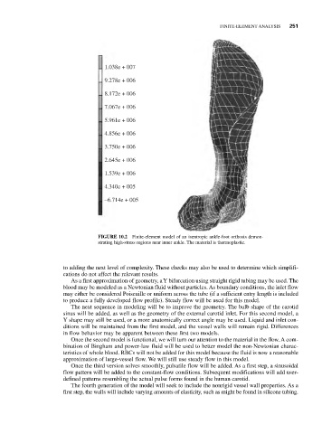
FIGURE 10.2 Finite-element model of an isentropic ankle-foot orthosis demon-
strating high-stress regions near inner ankle. The material is thermoplastic.
to adding the next level of complexity. These checks may also be used to determine which simplifi-
cations do not affect the relevant results.
As a first approximation of geometry, a Y bifurcation using straight rigid tubing may be used. The
blood may be modeled as a Newtonian fluid without particles. As boundary conditions, the inlet flow
may either be considered Poiseuille or uniform across the tube (if a sufficient entry length is included
to produce a fully developed flow profile). Steady flow will be used for this model.
The next sequence in modeling will be to improve the geometry. The bulb shape of the carotid
sinus will be added, as well as the geometry of the external carotid inlet. For this second model, a
Y shape may still be used, or a more anatomically correct angle may be used. Liquid and inlet con-
ditions will be maintained from the first model, and the vessel walls will remain rigid. Differences
in flow behavior may be apparent between these first two models.
Once the second model is functional, we will turn our attention to the material in the flow. A com-
bination of Bingham and power-law fluid will be used to better model the non-Newtonian charac-
teristics of whole blood. RBCs will not be added for this model because the fluid is now a reasonable
approximation of large-vessel flow. We will still use steady flow in this model.
Once the third version solves smoothly, pulsatile flow will be added. As a first step, a sinusoidal
flow pattern will be added to the constant-flow conditions. Subsequent modifications will add user-
defined patterns resembling the actual pulse forms found in the human carotid.
The fourth generation of the model will seek to include the nonrigid vessel wall properties. As a
first step, the walls will include varying amounts of elasticity, such as might be found in silicone tubing.