
Page 269 - Biomedical Engineering and Design Handbook Volume 1, Fundamentals
P. 269
246 BIOMECHANICS OF THE HUMAN BODY
This chapter gives an overview of the requirements and uses of FEA and similar codes for bio-
medical engineering analysis. The examples that will be used refer to FEA, but the techniques will
be the same for other systems, such as finite difference and computational fluid dynamics. The lit-
erature cited in this chapter gives a flavor of the breadth of information available and the studies
being undertaken. This listing is far from exhaustive because of the large number of ongoing efforts.
Numerous search engines are available to find abstracts relating to the subjects touched on in this
chapter.
A large number of software packages and a wide range of computational power are used in FEA
of the human body, ranging from basic personal computer (PC) programs and simplified constructs
to high-powered nonlinear codes and models that require extensive central processing unit (CPU)
time on supercomputers. Most of the examples in this chapter will be those run on desktop PCs.
The remainder of this chapter focuses on three basic concerns of a useful finite-element model:
the geometry, the material properties, and the boundary conditions.
10.2 GEOMETRIC CONCERNS
10.2.1 Two Dimensions versus Three Dimensions
The very first question is two-dimensional versus three-dimensional. While the human body is three-
dimensional (3D), many situations lend themselves to a successful two-dimensional (2D) analysis.
First approximations for implants (such as the
hip) may include 2D analysis. If the leg is in mid-
stance (not stair climbing), the loading pattern is 2D.
The head and proximal end of the femur are placed
in compression and bending, but there is minimal
out-of-plane loading. Long bone fracture fixation
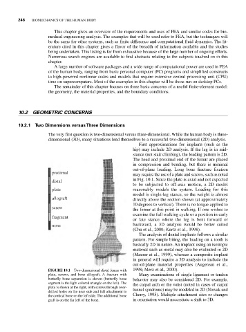
proximal
may require the use of a plate and screws, such as noted
in Fig. 10.1. Since the plate is axial and not expected
distal
to be subjected to off-axis motion, a 2D model
plate reasonably models the system. Loading for this
model is single-leg stance, so the weight is almost
allograft directly above the section shown (at approximately
10 degrees to vertical). There is no torque applied to
screw
the femur at this point in walking. If one wishes to
examine the full walking cycle or a position in early
fragment
or late stance where the leg is bent forward or
none backward, a 3D analysis would be better suited
(Chu et al., 2000; Kurtz et al., 1998).
The analysis of dental implants follows a similar
pattern. For simple biting, the loading on a tooth is
basically 2D in nature. An implant using an isotropic
material such as metal may also be evaluated in 2D
(Maurer et al., 1999), whereas a composite implant
in general will require a 3D analysis to include the
out-of-plane material properties (Augerean et al.,
FIGURE 10.1 Two-dimensional distal femur with 1998; Merz et al., 2000).
plate, screws, and bone allograft. A fracture with Many examinations of single ligament or tendon
butterfly bone separation is shown (butterfly bone behavior may also be considered 2D. For example,
segment is the light colored triangle on the left). The the carpal arch or the wrist (noted in cases of carpal
plate is shown at the right, with screws through over-
drilled holes on the near side and full attachment to tunnel syndrome) may be modeled in 2D (Nowak and
the cortical bone on the left side. The additional bone Cherry, 1995). Multiple attachment sites or changes
graft is on the far left of the bone. in orientation would necessitate a shift to 3D.