
Page 175 - Biomedical Engineering and Design Handbook Volume 2, Applications
P. 175
154 MEDICAL DEVICE DESIGN
Body
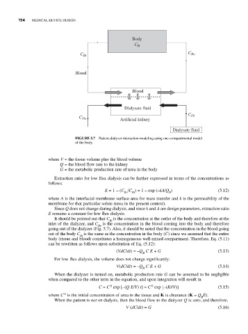
C B
C Bi C Bo
Blood
Blood
Dialysate fluid
C Di
C Do Artificial kidney
Dialysate fluid
FIGURE 5.7 Patient-dialyzer interaction modeling using one-compartmental model
of the body.
where V = the tissue volume plus the blood volume
Q = the blood flow rate to the kidney
G = the metabolic production rate of urea in the body
Extraction ratio for low flux dialysis can be further expressed in terms of the concentrations as
follows:
E = 1 – (C /C ) = 1 – exp (–kA/Q ) (5.12)
Bo Bi B
where A is the interfacial membrane surface area for mass transfer and k is the permeability of the
membrane for that particular solute (urea in the present context).
Since Q does not change during dialysis, and since k and A are design parameters, extraction ratio
E remains a constant for low flux dialysis.
It should be pointed out that C is the concentration at the outlet of the body and therefore at the
Bi
inlet of the dialyzer, and C is the concentration in the blood coming into the body and therefore
Bo
going out of the dialyzer (Fig. 5.7). Also, it should be noted that the concentration in the blood going
out of the body C is the same as the concentration in the body (C) since we assumed that the entire
Bi
body (tissue and blood) constitutes a homogeneous well-mixed compartment. Therefore, Eq. (5.11)
can be rewritten as follows upon substitution of Eq. (5.12):
(VdC/dt) = –Q CE + G (5.13)
B
For low flux dialysis, the volume does not change significantly:
V(dC/dt) = –Q CE + G (5.14)
B
When the dialyzer is turned on, metabolic production rate G can be assumed to be negligible
when compared to the other term in the equation, and upon integration will result in
0
0
C = C exp [–(QE/V) t] = C exp [–(Kt/V)] (5.15)
0
where C is the initial concentration of urea in the tissue and K is clearance (K = Q E).
B
When the patient is not on dialysis, then the blood flow to the dialyzer Q is zero, and therefore,
V (dC/dt) = G (5.16)