
Page 188 - Biomedical Engineering and Design Handbook Volume 2, Applications
P. 188
DESIGN OF CONTROLLED-RELEASE DRUG DELIVERY SYSTEMS 167
In Fig. 6.3, C is drug concentration in the reservoir or matrix compartment, C is solubility of
R
P
drug in the polymer phase, C is the concentration in diffusion layer, h is thickness of the mem-
m
D
brane, h is thickness of diffusion layer, and h + dh indicates the changing thickness of the deple-
P
P
d
tion zone of matrix.
In a reservoir system, if the active agent is in a saturated state, the driving force is kept constant
until it is no longer saturated. For matrix systems, because of the changing thickness of the deple-
10
tion zone, release kinetics is a function of the square root of time. A typical reservoir system for
transdermal delivery consists of a backing layer, a rate-limiting membrane, protective liner, and a
reservoir compartment. The drug is enclosed within the reservoir compartment and released through
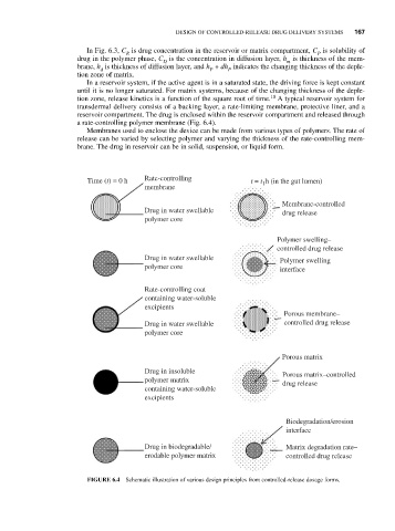
a rate-controlling polymer membrane (Fig. 6.4).
Membranes used to enclose the device can be made from various types of polymers. The rate of
release can be varied by selecting polymer and varying the thickness of the rate-controlling mem-
brane. The drug in reservoir can be in solid, suspension, or liquid form.
Time (t) = 0 h Rate-controlling t = t h (in the gut lumen)
1
membrane
Membrane-controlled
Drug in water swellable drug release
polymer core
Polymer swelling–
controlled drug release
Drug in water swellable
Polymer swelling
polymer core
interface
Rate-controlling coat
containing water-soluble
excipients
Porous membrane–
Drug in water swellable controlled drug release
polymer core
Porous matrix
Drug in insoluble
Porous matrix–controlled
polymer matrix
drug release
containing water-soluble
excipients
Biodegradation/erosion
interface
Drug in biodegradable/ Matrix degradation rate–
erodable polymer matrix controlled drug release
FIGURE 6.4 Schematic illustration of various design principles from controlled-release dosage forms.