
Page 436 - Biomedical Engineering and Design Handbook Volume 2, Applications
P. 436
414 SURGERY
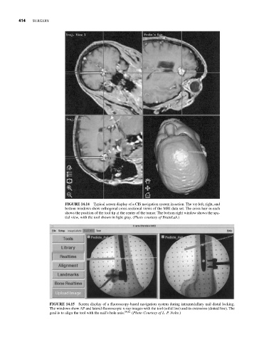
FIGURE 14.14 Typical screen display of a CIS navigation system in action. The top left, right, and
bottom windows show orthogonal cross-sectional views of the MRI data set. The cross hair in each
shows the position of the tool tip at the center of the tumor. The bottom right window shows the spa-
tial view, with the tool shown in light gray. (Photo courtesy of BrainLab.)
FIGURE 14.15 Screen display of a fluoroscopy-based navigation system during intramedullary nail distal locking.
The windows show AP and lateral fluoroscopic x-ray images with the tool (solid line) and its extension (dotted line). The
goal is to align the tool with the nail’s hole axis. 59,61 (Photo Courtesy of L. P. Nolte.)