
Page 331 - Biomimetics : Biologically Inspired Technologies
P. 331
Bar-Cohen : Biomimetics: Biologically Inspired Technologies DK3163_c012 Final Proof page 317 21.9.2005 11:54pm
Multifunctional Materials 317
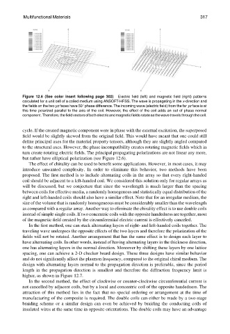
Figure 12.6 (See color insert following page 302) Electric field (left) and magnetic field (right) patterns
calculated for a unit cell of a coiled medium using ANSOFT-HFSS. The wave is propagating in the x-direction and
the fields on the two yz faces have 508 phase difference. The incoming wave (electric field) from the far yz face is at
this time polarized parallel to the axis of the coil. However, the effect of the coil adds an out of phase normal
component.Therefore,thefieldvectorsofbothelectricandmagneticfieldsrotateasthewavetravelsthroughthecell.
cycle. If the created magnetic component were in phase with the external excitation, the superposed
field would be slightly skewed from the original field. This would have meant that one could still
define principal axes for the material property tensors, although they are slightly angled compared
to the structural axes. However, the phase incompatibility creates rotating magnetic fields which in
turn create rotating electric fields. The principal propagating polarizations are not linear any more,
but rather have elliptical polarization (see Figure 12.6).
The effect of chirality can be used to benefit some applications. However, in most cases, it may
introduce unwanted complexity. In order to eliminate this behavior, two methods have been
proposed. The first method is to include alternating coils in the array so that every right-handed
coil should be adjacent to a left-handed coil. We considered this solution only for regular arrays as
will be discussed, but we conjecture that since the wavelength is much larger than the spacing
between coils for effective media, a randomly homogenous and statistically equal distribution of the
right and left-handed coils should also have a similar effect. Note that for an irregular medium, the
size of the volume that is randomly homogeneous must be considerably smaller than the wavelength
as compared with a regular array. Another way to eliminate the chirality effect is to use double coils
instead of simple single coils. If two concentric coils with the opposite handedness are together, most
of the magnetic field created by the circumferential electric current is effectively canceled.
In the first method, one can stack alternating layers of right- and left-handed coils together. The
traveling wave undergoes the opposite effects of the two layers and therefore the polarization of the
fields will not be rotated. Another arrangement that has the same effect is to design each layer to
have alternating coils. In other words, instead of having alternating layers in the thickness direction,
one has alternating layers in the normal direction. Moreover by shifting these layers by one lattice
spacing, one can achieve a 2-D checker board design. These three designs have similar behavior
and do not significantly affect the plasmon frequency, compared to the original chiral medium. The
design with alternating layers normal to the propagation direction is preferable, since the period
length in the propagation direction is smallest and therefore the diffraction frequency limit is
higher, as shown in Figure 12.7.
In the second method, the effect of clockwise or counter-clockwise circumferential current is
not cancelled by adjacent coils, but by a local and concentric coil of the opposite handedness. The
attraction of this method lies in the fact that no special ordering or arrangement at the time of
manufacturing of the composite is required. The double coils can either be made by a two-stage
braiding scheme or a similar design can even be achieved by braiding the conducting coils of
insulated wires at the same time in opposite orientations. The double coils may have an advantage