
Page 334 - Biomimetics : Biologically Inspired Technologies
P. 334
Bar-Cohen : Biomimetics: Biologically Inspired Technologies DK3163_c012 Final Proof page 320 21.9.2005 11:54pm
320 Biomimetics: Biologically Inspired Technologies
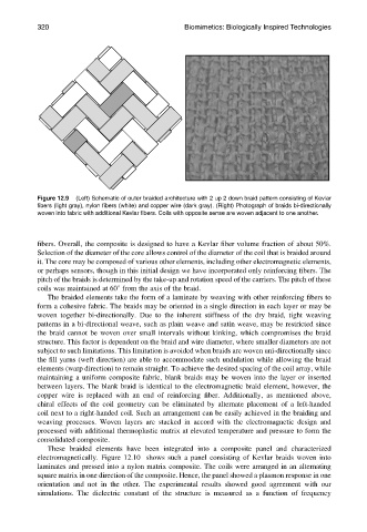
Figure 12.9 (Left) Schematic of outer braided architecture with 2 up 2 down braid pattern consisting of Kevlar
fibers (light gray), nylon fibers (white) and copper wire (dark gray). (Right) Photograph of braids bi-directionally
woven into fabric with additional Kevlar fibers. Coils with opposite sense are woven adjacent to one another.
fibers. Overall, the composite is designed to have a Kevlar fiber volume fraction of about 50%.
Selection of the diameter of the core allows control of the diameter of the coil that is braided around
it. The core may be composed of various other elements, including other electromagnetic elements,
or perhaps sensors, though in this initial design we have incorporated only reinforcing fibers. The
pitch of the braids is determined by the take-up and rotation speed of the carriers. The pitch of these
coils was maintained at 608 from the axis of the braid.
The braided elements take the form of a laminate by weaving with other reinforcing fibers to
form a cohesive fabric. The braids may be oriented in a single direction in each layer or may be
woven together bi-directionally. Due to the inherent stiffness of the dry braid, tight weaving
patterns in a bi-directional weave, such as plain weave and satin weave, may be restricted since
the braid cannot be woven over small intervals without kinking, which compromises the braid
structure. This factor is dependent on the braid and wire diameter, where smaller diameters are not
subject to such limitations. This limitation is avoided when braids are woven uni-directionally since
the fill yarns (weft direction) are able to accommodate such undulation while allowing the braid
elements (warp direction) to remain straight. To achieve the desired spacing of the coil array, while
maintaining a uniform composite fabric, blank braids may be woven into the layer or inserted
between layers. The blank braid is identical to the electromagnetic braid element, however, the
copper wire is replaced with an end of reinforcing fiber. Additionally, as mentioned above,
chiral effects of the coil geometry can be eliminated by alternate placement of a left-handed
coil next to a right-handed coil. Such an arrangement can be easily achieved in the braiding and
weaving processes. Woven layers are stacked in accord with the electromagnetic design and
processed with additional thermoplastic matrix at elevated temperature and pressure to form the
consolidated composite.
These braided elements have been integrated into a composite panel and characterized
electromagnetically. Figure 12.10 shows such a panel consisting of Kevlar braids woven into
laminates and pressed into a nylon matrix composite. The coils were arranged in an alternating
square matrix in one direction of the composite. Hence, the panel showed a plasmon response in one
orientation and not in the other. The experimental results showed good agreement with our
simulations. The dielectric constant of the structure is measured as a function of frequency