
Page 339 - Biomimetics : Biologically Inspired Technologies
P. 339
Bar-Cohen : Biomimetics: Biologically Inspired Technologies DK3163_c012 Final Proof page 325 21.9.2005 11:55pm
Multifunctional Materials 325
Cross-section of split ring element
2 x 0.0015" Gore speedBoard
0.032" Rogers 4003 +0.008" Rogers 4003
+ 2 x 0.0015" Gore speedBoard
(~0.014" total thickness)
Total thickness = 1.981 mm
= 0.078"
Cross-section at wire element
Figure 12.18 Dimensions for cross-sectioned view of NIM.
2
2
P ¼ VI ¼ I R ¼ V =R (12:3)
where P is power, V is voltage across the circuit element, I is direct current through the circuit, and
R is the resistance of the circuit element. Finite element computer simulation software, NISA, is
used to model the heating in conjunction with experimental testing. The heat transfer module of
NISA, known as NISA/HEAT, uses finite element methods to solve the heat conduction equation
for temperature based on a set of initial and boundary conditions.
Our thin wire arrayed composites typically have a spacing of 0.125 in. (3.175 mm) between
copper wires of 100 mm diameter. To simulate this geometry in NISA’s graphical interface, a unit
cell of 0.125 in. by 0.125 in. is constructed to represent a cross-section of the composite as shown in
Figure 12.20. To reduce calculations to a 2-D problem, the unit cell is assumed to have unit depth
and a constant cross-section along the length of the wire.
A square element mesh is applied to the unit cell, with the circular cross-section of wire
approximated by a square pattern of four elements. Boundary conditions are prescribed on the
8
4
Index
0
−4
7 8 9 10 11 12 13
Frequency (GHz)
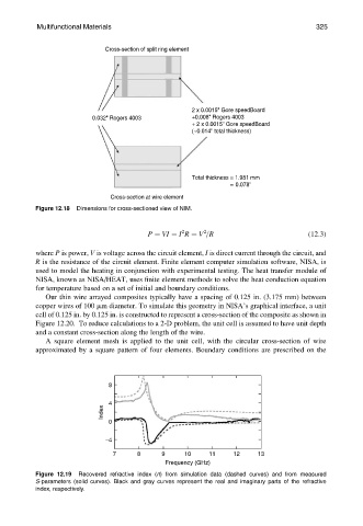
Figure 12.19 Recovered refractive index (n) from simulation data (dashed curves) and from measured
S-parameters (solid curves). Black and gray curves represent the real and imaginary parts of the refractive
index, respectively.