
Page 337 - Biomimetics : Biologically Inspired Technologies
P. 337
Bar-Cohen : Biomimetics: Biologically Inspired Technologies DK3163_c012 Final Proof page 323 21.9.2005 11:55pm
Multifunctional Materials 323
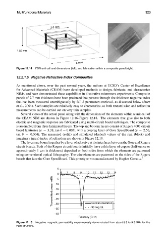
2.6 mm
1.59 mm
5 mm
Figure 12.14 FDR unit cell and dimensions (left); and fabrication within a composite panel (right).
12.2.1.5 Negative Refractive Index Composites
As mentioned above, over the past several years, the authors at UCSD’s Center of Excellence
for Advanced Materials (CEAM) have developed methods to design, fabricate, and characterize
NIMs, and have demonstrated these capabilities in illustrative microwave experiments. Composite
panels of 2.7 mm thickness have been produced that possess through-the-thickness negative index
that has been measured unambiguously by full S-parameters retrieval, as discussed below (Starr
et al., 2004). Such samples are relatively easy to characterize, as both transmission and reflection
measurements can be carried out on very thin samples.
Several views of the actual panel along with the dimensions of the elements within a unit cell of
the CEAM NIM are shown in Figure 12.16–Figure 12.18. The elements that give rise to both
electric and magnetic response are fabricated using multi-circuit board techniques. The composite
is assembled from three laminated layers. The top and bottom layers consist of Rogers 4003 circuit
board laminates (« ¼ 3.38, tan d ¼ 0:003), with a prepreg layer of Gore SpeedBoard (« ¼ 2.56,
tan d ¼ 0.004). The measured (solid) and simulated (dashed) values of the real (black) and
imaginary (gray) index of refraction are shown in Figure 12.19.
The layers are bound together by a layer of adhesive at the interfaces between the Gore and Rogers
circuit boards. Both of the Rogers circuit boards initially have a thin layer of copper (half-ounce or
approximately 1 mm in thickness) deposited on both sides from which the elements are patterned
using conventional optical lithography. The wire elements are patterned on the sides of the Rogers
boards that face the Gore SpeedBoard. This prototype was manufactured by Hughes Circuits. 2
5
6 7 8 9 10 11 12 13 14
0
Transmitted power (dB) −10
−5
−15
−20
−25
−30
90 deg rot.
−35 Normal orientation
−40
Freuency (GHz)
Figure 12.15 Negative magnetic permeability experimentally demonstrated from about 8.5 to 9.5 GHz for the
FDR structure.