
Page 332 - Biomimetics : Biologically Inspired Technologies
P. 332
Bar-Cohen : Biomimetics: Biologically Inspired Technologies DK3163_c012 Final Proof page 318 21.9.2005 11:54pm
318 Biomimetics: Biologically Inspired Technologies
Z
Z
Y
X
Y
X
(a) (b)
Z Z
Y
Y
X
(c) (d)
X
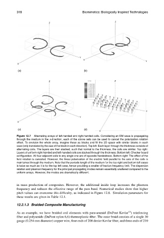
Figure 12.7 Alternating arrays of left-handed and right-handed coils. Considering an EM wave is propagating
through the medium in the x-direction, each of the above sets can be used to cancel the polarization rotation
effect. To envision the whole array, imagine these as blocks and fill the 3D space with similar blocks in each
case (only translated by the size of the block in each direction). Top left: Each layer through the thickness consists of
alternating coils. The layers are then stacked, such that normal to the thickness, the coils are similar. Top right:
Layers of uniform right-handed and left-handed coils are stacked through the thickness. Bottom left: Checker board
configuration. All four adjacent coils to any single one are of opposite handedness. Bottom right: The effect of the
field rotation is canceled. However, the linear polarization of the electric field parallel to the axis of the coils is
maintained through the medium. Note that the periodic length of the medium for the top right and bottom left cases
is twice as much as it is for the top left case, hence providing a smaller diffraction frequency limit. The dispersion
relation and plasmon frequency for the principal propagating modes remain essentially unaltered compared to the
uniform arrays. However, the modes are dramatically different.
in mass production of composites. However, the additional inside loop increases the plasmon
frequency and reduces the effective range of the pass band. Numerical studies show that higher
pitch values can overcome this difficulty, as indicated in Figure 12.8. Simulation parameters for
these results are given in Table 12.1.
12.2.1.3 Braided Composite Manufacturing
1
As an example, we have braided coil elements with para-aramid (DuPont Kevlar ) reinforcing
fiber and polyamide (DuPont nylon 6,6) thermoplastic fiber. The outer braid consists of a single 30
gauge (0.254 mm diameter) copper wire, four ends of 200 denier Kevlar fiber, and three ends of 210