
Page 352 - Biosystems Engineering
P. 352
Food Package Engineering 329
mechanical properties of blown film are generally better because
molecular orientation is achieved in both machine and transverse
directions. The stretching of film is controlled by adjusting the air
pressure inside the tube and haul-off speed. The expansion ratio
between die and blown film is 1.5:4 times the die diameter. The cost
for making a wide tubular film is much lower than for a wide cast
film due to the cost of precision grinding long chill rolls. However,
blown films may contain such defects as variations in film thicknesses,
surface defects, low tensile and impact strengths, and inferior optical
properties. Cast film extrusion results in less thickness variation, very
high outputs, and superior optical properties. Low-density polyeth-
ylene (LDPE) and high-density polyethylene (HDPE) are the most
commonly used polymers for making blown films. The multilayer
structure is obtained using multiple extruders; this process is known
as coextrusion. 2,6
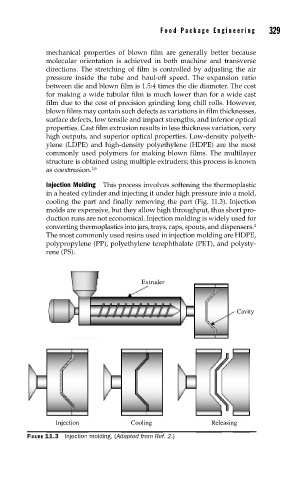
Injection Molding This process involves softening the thermoplastic
in a heated cylinder and injecting it under high pressure into a mold,
cooling the part and finally removing the part (Fig. 11.3). Injection
molds are expensive, but they allow high throughput, thus short pro-
duction runs are not economical. Injection molding is widely used for
converting thermoplastics into jars, trays, caps, spouts, and dispensers. 2
The most commonly used resins used in injection molding are HDPE,
polypropylene (PP), polyethylene terephthalate (PET), and polysty-
rene (PS).
Extruder
Cavity
Injection Cooling Releasing
FIGURE 11.3 Injection molding. (Adapted from Ref. 2.)