
Page 236 - Boiler_Operators_Handbook,_Second_Edition
P. 236
Maintenance 221
be removed.
Once you’ve removed the tube you should “dress
up” the hole, removing any tube metal stuck to it and
any corrosion that would accompany a leak or defective
rolled joint. Careful use of a file and sandpaper should
produce a smooth surface. The edges of the holes should
also be smoothed over to eliminate any sharp edges
that will cut the new tube. The tube ends should also be
dressed up to remove any corrosion for a tight metal to
metal fit.
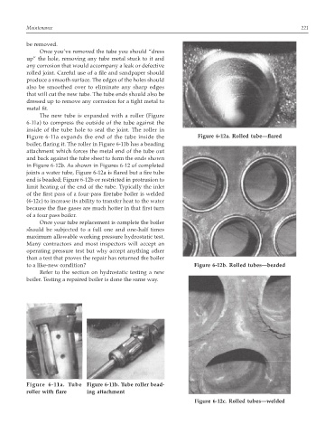
The new tube is expanded with a roller (Figure
6-11a) to compress the outside of the tube against the
inside of the tube hole to seal the joint. The roller in
Figure 6-11a expands the end of the tube inside the Figure 6-12a. Rolled tube—flared
boiler, flaring it. The roller in Figure 6-11b has a beading
attachment which forces the metal end of the tube out
and back against the tube sheet to form the ends shown
in Figure 6-12b. As shown in Figures 6-12 of completed
joints a water tube, Figure 6-12a is flared but a fire tube
end is beaded; Figure 6-12b or restricted in protrusion to
limit heating of the end of the tube. Typically the inlet
of the first pass of a four-pass firetube boiler is welded
(6-12c) to increase its ability to transfer heat to the water
because the flue gases are much hotter in that first turn
of a four pass boiler.
Once your tube replacement is complete the boiler
should be subjected to a full one and one-half times
maximum allowable working pressure hydrostatic test.
Many contractors and most inspectors will accept an
operating pressure test but why accept anything other
than a test that proves the repair has returned the boiler
to a like-new condition? Figure 6-12b. Rolled tubes—beaded
Refer to the section on hydrostatic testing a new
boiler. Testing a repaired boiler is done the same way.
Figure 6-11a. Tube Figure 6-11b. Tube roller bead-
roller with flare ing attachment
Figure 6-12c. Rolled tubes—welded