
Page 238 - Boiler_Operators_Handbook,_Second_Edition
P. 238
Maintenance 223
buy the product at his low prices. He was told thanks, The tack welds should all be checked to be sure none of
but no thanks and I’ve been very conscious of what I was them are cracked; a light tap with a hammer will nor-
buying thereafter. As far as I’m concerned any pipe that mally produce a ringing sound, any static is indicative
goes into a boiler room should have a stencil running of a crack that can’t be seen without magnification or
repeatedly along its length that begins “ANSI” and for other testing. Some procedures require the tack welds
B31.1 piping also “ASME” followed by a specification be replaced as the root pass is made but the tacks are
number and other data including a heat number which normally incorporated into the root pass.
makes the material traceable to the piping manufacturer.
Pipe fittings and valves must bear certain markings but
certificates aren’t required. They should, however, bear
a marking that identifies the manufacturer and the ap-
propriate ANSI specification.
As for the welder, the only way to determine the
quality without requiring RT (radiation testing, fre-
quently called X-ray) is visual examination by someone
who knows what to look for. Here’s what to look for:
Fit-up
The fit-up consists of matching the joint between
two pieces of pipe or a pipe and fitting or weld end
valve and attaching them with tack welds at no fewer
than four points evenly spaced around the pipe. The
two ends should be ground clean to gray metal (no rust,
paint, oil or other coating) for at least one-half inch from
Figure 6-13. Tee showing beveled end prep
the surfaces to be welded. The pipe should aligned such
that any differences in the inside edge of each pipe is
less than 1/16 inch (less for very high pressures and
temperatures). The joint should also be prepared in a
manner that conforms with the WPS (Welding Proce-
dure Specification) which the welder should be able to
show to you. Typically the ends of the pipe or fitting is
ground to a bevel as shown in Figure 6-13. That’s the
standard preparation for an open butt welded joint
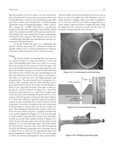
where the two ends of the pipe are positioned so a cross
section of the fit-up joint would look like that in Figure
6-14. Four tack welds are typically used and located at
quarter points straddling the vertical and horizontal
centerlines. A keyhole is formed at the end of each tack
weld providing a starting point for the rest of the root Figure 6-14. Cross section of fit-up
pass. This arrangement permits the welder to fill in be-
tween the two ends to provide a complete weld like the
cross-section diagram in Figure 6-17. A section through
a weld wouldn’t look like that because you shouldn’t
be able to see the black outlines shown in Figure 6-17.
That’s because the pipe and weld metal should be fused
together so you can’t tell them apart. The joint should
be inspected by someone other than those preparing
the joint and should incorporate use of the gage shown
in Figure 6-15a to check for the appropriate bevel and
internal alignment. Figure 6-15b shows use of the gage
to check for internal misalignment and a proper bevel. Figure 6-15a. Welding inspection gage