
Page 204 - Bridge and Highway Structure Rehabilitation and Repair
P. 204
CHAPTER 4 AN ANALYTICAL APPROACH TO FRACTURE AND FAILURE 179
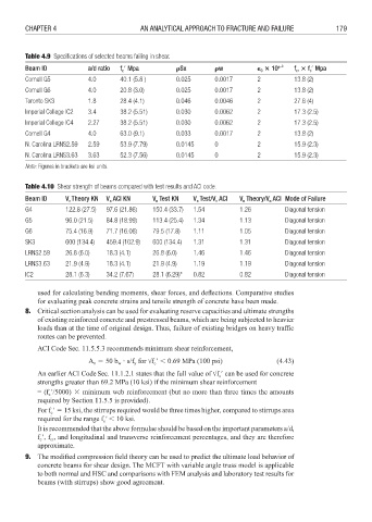
Table 4.9 Specifi cations of selected beams failing in shear.
Beam ID a/d ratio f 1 Mpa Sx w 0 10 e –3 f f 1 Mpa
c
cr
c
Cornell G5 4.0 40.1 (5.8 ) 0.025 0.0017 2 13.8 (2)
Cornell G6 4.0 20.8 (3.0) 0.025 0.0017 2 13.8 (2)
Toronto SK3 1.8 28.4 (4.1) 0.046 0.0046 2 27.6 (4)
Imperial College IC2 3.4 38.2 (5.51) 0.030 0.0062 2 17.3 (2.5)
Imperial College IC4 2.27 38.2 (5.51) 0.030 0.0062 2 17.3 (2.5)
Cornell G4 4.0 63.0 (9.1) 0.033 0.0017 2 13.8 (2)
N. Carolina LRNS2.59 2.59 53.9 (7.79) 0.0145 0 2 15.9 (2.3)
N. Carolina LRNS3.63 3.63 52.3 (7.56) 0.0145 0 2 15.9 (2.3)
Note: Figures in brackets are ksi units.
Table 4.10 Shear strength of beams compared with test results and ACI code.
Beam ID V Theory KN V ACI KN V Test KN V Test/V ACI V Theory/V ACI Mode of Failure
n
n
n
n
n
n
n
G4 122.8 (27.5) 97.6 (21.86) 150.4 (33.7) 1.54 1.26 Diagonal tension
G5 96.0 (21.5) 84.8 (18.99) 113.4 (25.4) 1.34 1.13 Diagonal tension
G6 75.4 (16.9) 71.7 (16.06) 79.5 (17.8) 1.11 1.05 Diagonal tension
SK3 600 (134.4) 459.4 (102.9) 600 (134.4) 1.31 1.31 Diagonal tension
LRNS2.59 26.8 (6.0) 18.3 (4.1) 26.8 (6.0) 1.46 1.46 Diagonal tension
LRNS3.63 21.9 (4.9) 18.3 (4.1) 21.9 (4.9) 1.19 1.19 Diagonal tension
IC2 28.1 (6.3) 34.2 (7.67) 28.1 (6.29)* 0.82 0.82 Diagonal tension
used for calculating bending moments, shear forces, and defl ections. Comparative studies
for evaluating peak concrete strains and tensile strength of concrete have been made.
8. Critical section analysis can be used for evaluating reserve capacities and ultimate strengths
of existing reinforced concrete and prestressed beams, which are being subjected to heavier
loads than at the time of original design. Thus, failure of existing bridges on heavy traffi c
routes can be prevented.
ACI Code Sec. 11.5.5.3 recommends minimum shear reinforcement,
A 3 50 b s/f for f 1 : 0.69 MPa (100 psi) (4.43)
v
w
c
y
An earlier ACI CodeSec. 11.1.2.1 states that the full value of f 1 can be used for concrete
c
strengths greater than 69.2 MPa (10 ksi) if the minimum shear reinforcement
= (f 1/5000) 8 minimum web reinforcement (but no more than three times the amounts
c
required by Section 11.5.5 is provided).
For f 1 3 15 ksi, the stirrups required would be three times higher, compared to stirrups area
c
required for the range f 1: 10 ksi.
c
It is recommended that the above formulae should be based on the important parameters a/d,
f 1, f , and longitudinal and transverse reinforcement percentages, and they are therefore
cr
c
approximate.
9. The modified compression field theory can be used to predict the ultimate load behavior of
concrete beams for shear design. The MCFT with variable angle truss model is applicable
to both normal and HSC and comparisons with FEM analysis and laboratory test results for
beams (with stirrups) show good agreement.