
Page 205 - Bridge and Highway Structure Rehabilitation and Repair
P. 205
180 SECTION 2 STRENGTHENING AND REPAIR WORK
The following formula may be used:
f − f f + f
03 tan −1 d L 3 tan −1 dt t (4.44)
f − f f + f
d t dt L
4.16.4 Fracturing Truss Model as an Alternate to MCFT
Recent research results reported by Bazant and Shah utilize a two-parameter fracture model,
crack band, and fictitious crack models. Size effects and bond effects can be studied from non-
linear elastic fracture mechanics models using fracture-based finite element codes.
In the FTM, shear strength is based on fracture toughness, and it is assumed cracks are
distributed throughout the concrete web. This assumption is more consistent with actual beam
failure than the MCFT assumption that cracks are confined to critical sections only.
In addition to common parameters in the two methods, such as f 1 and E 1, the strength of
c c
beam in FTM depends on:
1. Fracture energy resulting from aggregate size.
2. Proportion of specimen dimensions.
3. Geometric similarity of beam shapes.
Also, shear strength is a function of bond effects, size effects, and the compression failure in
inclined compression struts. Size effects and bond effects have practical importance in the design
of concrete beam sections. FTM has the potential to be a powerful tool in future design codes.
4.17 SHEAR DESIGN FOR REINFORCED CONCRETE AND PRESTRESSED BEAMS
4.17.1 Shear Design for the Lifting and Erection of Prestressed Concrete Beams
A dynamic allowance factor for wind gust is applied for estimating the crane capacity.
Two cranes may be required for lifting. The capacity of beam cross section, hooks, and anchor-
age length inside concrete needs to be checked using MCFT. A program may be developed in
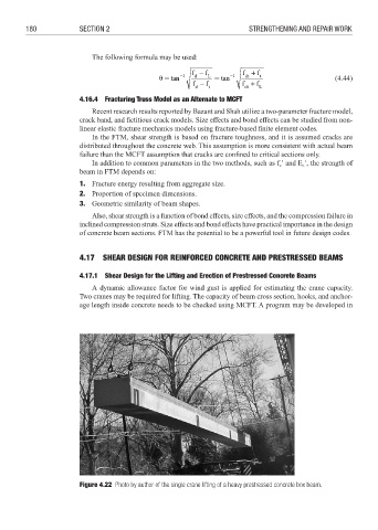
Figure 4.22 Photo by author of the single crane lifting of a heavy prestressed concrete box beam.