
Page 247 - Bridge and Highway Structure Rehabilitation and Repair
P. 247
222 SECTION 2 STRENGTHENING AND REPAIR WORK
5.6.8 Superstructure Design for Fatigue Stress (Applicable to Steel Girders)
1. Fatigue limit state.
2. Category C fatigue details and at sections:
• Refer to Section 6.6.1.2.5
• Refer to Section 6.10.4.3 for web fatigue stress limit for moment
• Refer to Section 6.10.4.4 for web fatigue stress limit for shear
• Refer to Section 6.10.7.4 for stud and channel shear connectors fatigue.
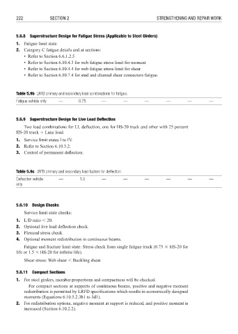
Table 5.9b LRFD primary and secondary load combinations for fatigue.
Fatigue vehicle only — 0.75 — — — — — —
5.6.9 Superstructure Design for Live Load Defl ection
Two load combinations for LL deflection, one for HS-20 truck and other with 25 percent
HS-20 truck 4 Lane load.
1. Service limit states I to IV.
2. Refer to Section 6.10.3.2.
3. Control of permanent defl ection.
Table 5.9c LRFD primary and secondary load factors for defl ection.
Defl ection vehicle — 1.0 — — — — — —
only
5.6.10 Design Checks
Service limit state checks:
1. L/D ratio : 20.
2. Optional live load defl ection check.
3. Flexural stress check.
4. Optional moment redistribution in continuous beams.
Fatigue and fracture limit state: Stress check from single fatigue truck (0.75 8 HS-20 for
life or 1.5 8 HS-20 for infi nite life).
Shear stress: Web shear : Buckling shear.
5.6.11 Compact Sections
1. For steel girders, member proportions and compactness will be checked.
For compact sections at supports of continuous beams, positive and negative moment
redistribution is permitted by LRFD specifications which results in economically designed
moments (Equations 6.10.5.2.3b1 to 3d1).
2. For redistribution options, negative moment at support is reduced, and positive moment is
increased (Section 6.10.2.2).