
Page 248 - Bridge and Highway Structure Rehabilitation and Repair
P. 248
CHAPTER 5 LOAD AND RESISTANCE FACTOR RATING AND REDESIGN 223
5.6.12 Non-Compact Sections
For non-compact sections, lateral torsional buckling applies. Moment redistribution facility
is not applicable. The following equations are applicable:
Braced compression fl ange 6 Yielding limit: R is hybrid girder reduction factor for web
h
yielding
1. f 4 f :> R F
bu l f h yc
Web buckling limit
2. f :> F
bu f ctw
Strength limit: 1/3 based on inelastic analysis
3. f 4 f /3 :> F
bu l f nc
Braced tension fl ange 6 Yielding limit: No instability
1. f 4 f :> R F
bu l f h yf
No lateral bending: Continuously braced fl ange
2. f :> R F
bu f h yf
5.7 CONSTRUCTION LOADS AND LOAD COMBINATIONS
5.7.1 Design of Temporary Works
1. Design of temporary works during construction: Design criteria for falsework and formwork
will conform to the AASHTO Guide Design Specifications for Bridge Temporary Works.
2. The following construction load combinations based on strength I, III, and V conditions
may be used. Construction loads include:
• Weight of equipment
• Weight of formwork
• Weight of materials.
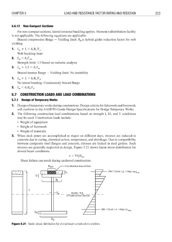
3. When deck pours are accomplished in stages on different days, stresses are induced in
concrete due to curing, chemical action, temperature, and shrinkage. Due to compatibility
between composite steel flanges and concrete, stresses are locked in steel girders. Such
stresses are generally neglected in design. Figure 5.21 shows linear stress distribution for
shored beam conditions.
3 VQ/I tran
Shear failure can result during unshored construction.
n
Const. LL. Imp. nI tran
Const. LL. Imp.
I tran
Figure 5.21 Elastic stress distribution for shored beam construction condition.