
Page 263 - Bridge and Highway Structure Rehabilitation and Repair
P. 263
238 SECTION 2 STRENGTHENING AND REPAIR WORK
Stress criteria: There are several considerations in bridge design, of which avoiding over-
stress is the most important. The magnitude of stress depends upon response of the material
and its age.
The response of material is based on physical properties such as elastic modulus and modulus
of rupture and on the size and shape of the member. It is usually expressed as:
1. Elastic stress.
2. Yield stress.
3. Plastic stress.
4. Failure or collapse stress.
Generally, the extreme limit of elastic stress is yield stress, the extreme limit of yield
stress is plastic stress, and the extreme limit of plastic stress is failure or collapse stress.
• Glass, ceramic, or plastics display fragile behavior
• Concrete displays brittle behavior
• Steel displays ductile behavior.
Hence, glass needs to be reinforced with wire, plastics reinforced with fiber, and concrete
made composite reinforced with rods.
5. Stress history is based on applied loads. Evaluation of various stages in the life of bridge
components and chronological assessment of their performance are required so that limits
can be placed either in design or in practice to prevent failure. Sources of stress include:
• Fabrication stress
• Transportation stress
• Erection stress
• Stresses resulting from maintenance loads.
6. Stresses at demolition or at failure: Many bridge failures can be avoided by paying attention
to changes in design technology and details. For example, new concrete materials such as
lightweight and heavyweight aggregates, structural plastics, and glass composites have dif-
ferent unit weights than conventional wet concrete. Such materials display nonhomogeneous
and non-isotropic behavior. Current load factors and resistance factors need to be modifi ed
in the light of experimental results.
6.2.2 Internal and External Effects
Factored resistance at any location of structure 9$ factored load effects acting at that
location.
Factored resistance 3 ) R
n
) R 9 $ Q when selected is maximum
n i i i i .
) R 9$ Q / when selected is minimum.
n i i i i
Factored resistance 3 ) R ,) 3 Resistance factor
n
3 Load factor (AASHTO Table 3.4.1-1 and Table 3.4.1-2)
i
Q 3 Nominal force effect
i
R 3 Nominal resistance—itis the mean or an identifi ed level of strength.
n
3 Load modifi er
i
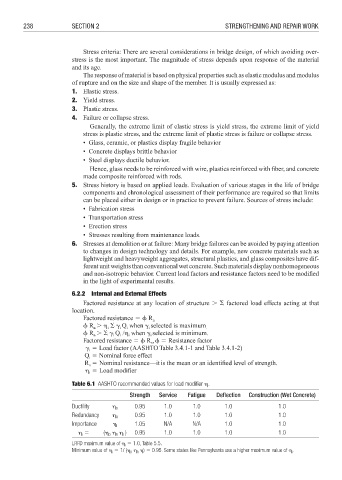
Table 6.1 AASHTO recommended values for load modifi er .
Strength Service Fatigue Deflection Construction (Wet Concrete)
Ductility D 0.95 1.0 1.0 1.0 1.0
Redundancy R 0.95 1.0 1.0 1.0 1.0
Importance I 1.05 N/A N/A 1.0 1.0
3 ( ) 0.95 1.0 1.0 1.0 1.0
i
I
D
R
LRFD maximum value of i 3 1.0, Table 5.5.
Minimum value of i 3 1/ ( D R ) 3 0.95. Some states like Pennsylvania use a higher maximum value of i .