
Page 126 - Build Your Own Combat Robot
P. 126
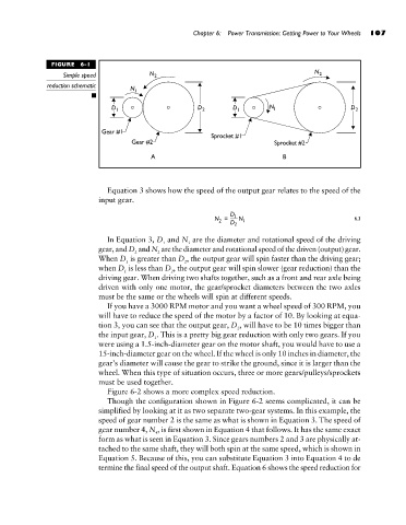
FIGURE  6-1                        Chapter 6:  Power Transmission: Getting Power to Your Wheels  107
                            Simple speed
                       reduction schematic


                                      Equation 3 shows how the speed of the output gear relates to the speed of the
                                    input gear.

                                                                                                    6.3


                                      In Equation 3, D and N are the diameter and rotational speed of the driving
                                                    1     1
                                    gear, and D and N are the diameter and rotational speed of the driven (output) gear.
                                                   2
                                             2
                                    When D is greater than D , the output gear will spin faster than the driving gear;
                                           1              2
                                    when D is less than D , the output gear will spin slower (gear reduction) than the
                                           1          2
                                    driving gear. When driving two shafts together, such as a front and rear axle being
                                    driven with only one motor, the gear/sprocket diameters between the two axles
                                    must be the same or the wheels will spin at different speeds.
                                      If you have a 3000 RPM motor and you want a wheel speed of 300 RPM, you
                                    will have to reduce the speed of the motor by a factor of 10. By looking at equa-
                                    tion 3, you can see that the output gear, D , will have to be 10 times bigger than
                                                                       2
                                    the input gear, D . This is a pretty big gear reduction with only two gears. If you
                                                  1
                                    were using a 1.5-inch-diameter gear on the motor shaft, you would have to use a
                                    15-inch-diameter gear on the wheel. If the wheel is only 10 inches in diameter, the
                                    gear’s diameter will cause the gear to strike the ground, since it is larger than the
                                    wheel. When this type of situation occurs, three or more gears/pulleys/sprockets
                                    must be used together.
                                      Figure 6-2 shows a more complex speed reduction.
                                      Though the configuration shown in Figure 6-2 seems complicated, it can be
                                    simplified by looking at it as two separate two-gear systems. In this example, the
                                    speed of gear number 2 is the same as what is shown in Equation 3. The speed of
                                    gear number 4, N , is first shown in Equation 4 that follows. It has the same exact
                                                  4
                                    form as what is seen in Equation 3. Since gears numbers 2 and 3 are physically at-
                                    tached to the same shaft, they will both spin at the same speed, which is shown in
                                    Equation 5. Because of this, you can substitute Equation 3 into Equation 4 to de
                                    termine the final speed of the output shaft. Equation 6 shows the speed reduction for