
Page 127 - Build Your Own Combat Robot
P. 127
Build Your Own Combat Robot
108
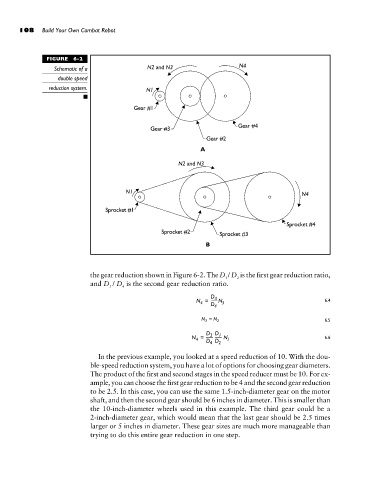
FIGURE 6-2
Schematic of a
double speed
reduction system.
the gear reduction shown in Figure 6-2. The D / D is the first gear reduction ratio,
1 2
and D / D is the second gear reduction ratio.
3 4
6.4
6.5
6.6
In the previous example, you looked at a speed reduction of 10. With the dou-
ble-speed reduction system, you have a lot of options for choosing gear diameters.
The product of the first and second stages in the speed reducer must be 10. For ex-
ample, you can choose the first gear reduction to be 4 and the second gear reduction
to be 2.5. In this case, you can use the same 1.5-inch-diameter gear on the motor
shaft, and then the second gear should be 6 inches in diameter. This is smaller than
the 10-inch-diameter wheels used in this example. The third gear could be a
2-inch-diameter gear, which would mean that the last gear should be 2.5 times
larger or 5 inches in diameter. These gear sizes are much more manageable than
trying to do this entire gear reduction in one step.