
Page 163 - Build Your Own Combat Robot
P. 163
Build Your Own Combat Robot
144
ESCs. These controllers typically have only one or two FETs per leg of the
H-bridge, and most use a small extruded aluminum heat sink to dissipate the heat
from the FETs.
These controllers are intended for use in single-motor models. The initial units had
only forward speed as model boats and cars rarely ever had to reverse. Their technical
specifications were geared for the model racing hobby using NiCad batteries and
were written accordingly for non-technical people. To this day, most of the manufac-
turers still specify the “number of cells,” rather than the minimum and maximum
voltage requirements of a particular ESC, and use the term“number of windings” (on
the motor’s armature) as a measurement of current capacity. This can be confusing to
those who feel comfortable with the terms “volts” and “amps.”
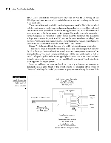
Figure 7-12 shows a block diagram of a hobby electronic speed controller.
The number of cells designation literally means you can multiply that number
by 1.2 volts to get the actual minimum and maximum voltage requirements of the
particular ESC. You must remember that many of the cars used stacks of AA or
sub-C cells packaged in a shrink-wrapped plastic cover and were rated at about
9.6 volts (eight cells) maximum. Few cars used 10 cells to arrive at 12 volts, the basic
starting point for robot systems.
Many model boats use motors that draw relatively high currents, as do most
competition race cars. Most of the specifications for standard ESC’s speak of
“16-turn” windings for the DC permanent magnet motors as being the norm. This
FIGURE 7-12
Block diagram of a
hobby electronic
speed controller.