
Page 160 - Build Your Own Combat Robot
P. 160
Chapter 7:
Controlling Your Motors
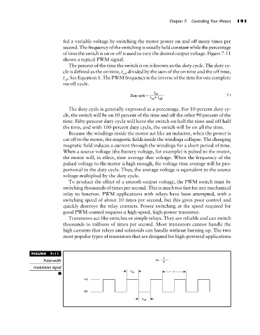
fed a variable voltage by switching the motor power on and off many times per 141
second. The frequency of the switching is usually held constant while the percentage
of time the switch is on or off is used to vary the desired output voltage. Figure 7-11
shows a typical PWM signal.
The percent of the time the switch is on is known as the duty cycle. The duty cy-
cle is defined as the on time, t , divided by the sum of the on time and the off time,
on
t . See Equation 1. The PWM frequency is the inverse of the time for one complete
off
on-off cycle.
7.1
The duty cycle is generally expressed as a percentage. For 10-percent duty cy-
cle, the switch will be on 10 percent of the time and off the other 90 percent of the
time. Fifty percent duty cycle will have the switch on half the time and off half
the time, and with 100-percent duty cycle, the switch will be on all the time.
Because the windings inside the motor act like an inductor, when the power is
cut off to the motor, the magnetic fields inside the windings collapse. The changing
magnetic field induces a current through the windings for a short period of time.
When a source voltage (the battery voltage, for example) is pulsed to the motor,
the motor will, in effect, time average that voltage. When the frequency of the
pulsed voltage to the motor is high enough, the voltage time average will be pro-
portional to the duty cycle. Thus, the average voltage is equivalent to the source
voltage multiplied by the duty cycle.
To produce the effect of a smooth output voltage, the PWM switch must be
switching thousands of times per second. This is much too fast for any mechanical
relay to function. PWM applications with relays have been attempted, with a
switching speed of about 10 times per second, but this gives poor control and
quickly destroys the relay contacts. Power switching at the speed required for
good PWM control requires a high-speed, high-power transistor.
Transistors act like switches or simple relays. They are reliable and can switch
thousands to millions of times per second. Most transistors cannot handle the
high currents that relays and solenoids can handle without burning up. The two
most popular types of transistors that are designed for high-powered applications
FIGURE 7-11
Pulse-width
modulation signal