
Page 157 - Build Your Own Combat Robot
P. 157
Build Your Own Combat Robot
138
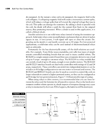
de-energized. At the instant a relay coil is de-energized, the magnetic field in the
coil collapses. A collapsing magnetic field will create a momentary current spike,
which will induce a voltage spike that will exceed the original voltage that was in
the coil. This spike can damage the transistor. By adding a diode in parallel with
the coil, the diode will allow a path for the current flow back to the original
source, thus protecting transistor. When a diode is used in this application, it is
called a flyback diode.
Another solution is to use solid-state relays instead of using the transistor ap-
proach. Solid-state relays come in small plastic enclosures that are about 2 inches
square in size. A low-current, 5-volt signal will open or close the circuit. De-
pending on the model, it can handle currents up to 40 amps. For low-powered
applications, a solid-state relay can be used instead of electromechanical relays
such as solenoids.
Fortunately for the less electronically astute, off-the-shelf solutions are avail-
able. For example, Team Delta (www.teamdelta.com) sells four types of simple
remote controlled switching boards that are used in many combat robots. The
RCE200 is a single-output control board that uses a transistor driver to run a load
of up to 9 amps—enough to run most relays. The RCE210 is a relay module that
can switch a load of up to 24 amps, enough to run smaller motors. The RCE220
and RCE225 interface boards are dual-relay controllers with ratings of 12 and 24
amps, respectively. These controllers can switch two independent motors or can be
wired in an H-bridge configuration to run one motor in forward and reverse. The
RCE220 and RDE225 boards can also be used as a switch to control the coils on
larger solenoids to control a higher-powered motor, or they can be configured as
an H-bridge for low-powered motors. Figure 7-10 illustrates this type of a setup.
When using relays to drive motors, it is recommended that you use fuses be-
tween the relays and the batteries for all non-drive motors. Due to the harsh envi-
ronment combat robots operate in, shock impacts of weapons damage may cause
a relay to momentarily short out. If this happens, the batteries will be destroyed.
FIGURE 7-9
Schematic showing
how a transistor
can be used to turn
a relay on or off.